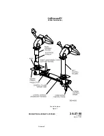
A control column shaker motor is attached to the pilot and copilot
control columns. When activated by a stall warning computer, the
motor drives an off-center weight that vibrates the control column.
Activation of one motor affects both control columns due to their
mechanical interconnection.
(5) Stall Barrier System:
A stall barrier system (control column pusher) is incorporated in the
pitch flight control system to prevent a stall by forcing the control
columns forward when the flight crew fails to respond to either visual
indications or to the control column vibrations that warn of
impending stall. The system consists of two normally closed stall
barrier valves and an actuating cylinder that is mechanically linked
to the elevator actuator input sector. One valve receives signals
from the No. 1 stall warning computer while the other valve receives
signals from the No. 2 stall warning computer. If one system fails,
the remaining system is capable of operating the system.
When a high AOA is reached, the control column shaker motors are
activated. When a more severe AOA is reached, the control column
pusher trip detector activates its respective stall barrier valve. The
activation signal will originate from whichever system is operating -
No. 1, No. 2 or both. When a stall barrier valve is activated,
Combined (or Utility) hydraulic system pressure is ported to the
extend side of the stall barrier actuating cylinder. As the cylinder
extends, it applies an input to the elevator actuator input sector. This
input causes the elevator actuator to drive the elevator trailing edges
down;
the
control
column
drives
forward
accordingly,
to
approximately one inch forward of neutral. When AOA has
decreased more than one degree, the stall barrier system
disengages.
The force generated by the stall barrier system is sufficient to
overcome any autopilot force, however, the system can be manually
overcome by the flight crew.
The stall barrier system can be deactivated by pressing the BARR
DISC button on either control wheel. The BARR DISC button also
serves as the autopilot disconnect button, thus is also labeled A/P
DISC accordingly. Deactivation of the stall barrier system is also
possible through selection of the STALL BARRIER switchlight to
OFF. The switchlight is located on the cockpit center pedestal just
below the left HP fuel cock. An amber OFF legend in the switchlight
will illuminate when the system is deactivated and will extinguish
when activated.
(6) Stall Warning / Stall Barrier System Test:
The stall warning / stall barrier system is normally tested by the flight
crew on the first flight of the day or every eight hours of flight time.
The test is performed only on the ground and cannot be tested in
flight. It consists of the following steps:
(a) Select the STALL BARRIER switch to on. Verify amber OFF
legend is extinguished.
(b) On both the pilot’s and copilot’s display controllers, depress
the TEST function key.
OPERATING MANUAL
PRODUCTION AIRCRAFT SYSTEMS
2A-27-00
Page 12
January 31/02
Revision 6
Summary of Contents for IV
Page 17: ...Pitch Trim Controls Figure 5 OPERATING MANUAL 2A 27 00 Page 21 22 January 31 02 ...
Page 32: ...Rudder Pedals Forward Linkage Figure 13 OPERATING MANUAL 2A 27 00 Page 39 40 January 31 02 ...
Page 50: ...Flaps Simplified Block Diagram Figure 18 OPERATING MANUAL 2A 27 00 Page 61 62 January 31 02 ...


