In the event of a malfunction or failure of internal rudder actuator load
limiting, redundant limiting is provided by an additional external load
limiting valve installed upstream of the rudder actuator. With this
configuration, continuous rudder load limiting is afforded as either load
limiting valve (internal or external) will limit output pressure. The external
load limiting valve limits total hydraulic pressure to a maximum of 2,650
(Combined and Flight systems) to the rudder actuator.
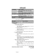
The external load limiting valve is checked by observing CAS for display of
an amber SNGL RUDDER LIMIT caution message. Proper operation of the
valve is indicated by display of the message during the following sequence:
•
Before starting engines (power on) — message displayed
•
Right engine only operating — message displayed
•
Both engines operating — message not displayed
Proper operation of the valve can also be verified during the following
sequence:
•
0 psi Combined pressure / 3,000 psi Flight pressure — message
displayed
•
3,000 psi Combined pressure / 3,000 psi Flight pressure —
message not displayed
•
3,000 psi Combined pressure / 0 psi Flight pressure — message not
displayed
F. Yaw Damper System:
A series mode yaw damper is incorporated into the rudder actuator.
Controlled
by
the
autopilot,
the
yaw
damper
provides
stability
augmentation by automatically counteracting any dutch roll tendency within
the aircraft. The system is referred to as a series mode system in that no
feedback is provided through the rudder pedals.
The yaw damper system consists of a solenoid-operated shutoff valve,
transfer valve, servo ram and summing lever / transducer. Electrical power
is supplied to the system through the Right Main and Essential 28 VDC
buses. Hydraulic power is supplied to the system by the Flight hydraulic
system only.
Located on the pilot’s flight panel, the YAW DAMP ENG / DISENG switch
engages or disengages the yaw damper. With the yaw damper engaged
(amber DISEN switch legend extinguished), 28 VDC power energizes the
solenoid-operated shutoff valve to the open position. Flight hydraulic
system pressure then flows to the transfer valve. Hydraulic pressure flow
and volume through the transfer valve is controlled by the torque motor
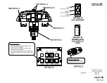
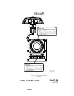
using a jet pipe / receiver pipe arrangement. The yaw damper / pitch trim
control panel is shown in Figure 9.
Depending on commands provided by the autopilot, the torque motor
positions a jet pipe to direct hydraulic pressure to two receiver pipes inside
the transfer valve. If equal commands are sent by the autopilot, the jet pipe
remains in a centered, or null, position. When unequal commands are sent,
the torque motor deflects the jet pipe in the necessary direction to supply
more pressure to one receiver pipe than the other. This shifts the transfer
valve spool and hydraulic pressure flows from the transfer valve to the
servo ram.
OPERATING MANUAL
PRODUCTION AIRCRAFT SYSTEMS
2A-27-00
Page 33
January 31/02
Revision 6
Summary of Contents for IV
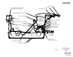
Page 17: ...Pitch Trim Controls Figure 5 OPERATING MANUAL 2A 27 00 Page 21 22 January 31 02 ...
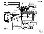
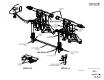
Page 32: ...Rudder Pedals Forward Linkage Figure 13 OPERATING MANUAL 2A 27 00 Page 39 40 January 31 02 ...
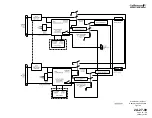
Page 50: ...Flaps Simplified Block Diagram Figure 18 OPERATING MANUAL 2A 27 00 Page 61 62 January 31 02 ...

