output crank. The damper is designed to sense control column movement
and provide a counteracting damping force or artificial feel. Damping force
is generated in proportion to control column velocity. Should the eddy
current damper jam or fail, its internal clutch releases to allow control
column movement.
B. Mechanical Actuation System:
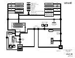
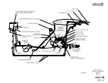
(See Figure 3.)
Control column inputs are transmitted rearward through a system of push-
pull rods, bellcranks, cables and a sector assembly to an input cable sector
below the base of the vertical stabilizer in the tail compartment. Connected
to the input cable sector are the elevator actuator, autopilot servo and
stability springs. Final output of the sector is to the elevator actuator input
lever.
Movement of the actuator input lever displaces the elevator actuator’s
servo control valve, directing Combined and Flight hydraulic system
pressure to the actuator cylinders. When under pressure, the actuator body
moves while the its piston remains motionless. Movement of the actuator
body in turn moves its output crank. Output crank movement is transmitted
upward and aft to the left and right elevators through a system of push-pull
rods and cranks, resulting in the desired elevator deflection.
Stability springs, commonly referred to as down springs, provide
approximately 13 pounds of pull on the control columns. This pulling force
keeps pilot feel forces out of the friction band at low airspeeds.
C. Hydraulic Boost System:
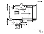
The elevator actuator is a dual tandem actuator consisting of two pistons
secured to a common shaft. The pistons move inside a common cylinder
divided to create two separate cylinders. One cylinder receives Flight
hydraulic system pressure while the other cylinder receives Combined
hydraulic system pressure.
Mechanical movement of the actuator input lever moves the servo control
valve from its neutral position. The servo control valve then directs
hydraulic pressure to one of the actuator’s two cylinders and connects
each cylinder’s opposite side to return. When the elevator reaches the
desired deflection, the servo control valve shifts to its neutral position to
lock hydraulic pressure within the actuator, in effect preventing further
surface movement.
The elevator actuator also has an internal hydraulic damper that provides
damping force proportional to the square of its input velocity. This damping
action ensures operational stability for the elevators when hydraulically
boosted whereby a portion of the actuator’s output is fed back to the input
system.
D. Manual Reversion System:
During normal flight operations, the Combined and Flight hydraulic
systems each supply and maintain 3000 psi to the elevator actuator. Loss
of system pressure due to a single system failure has no effect on
operation of the pitch flight control system.
Loss of system pressure from both hydraulic systems will automatically
revert the pitch flight control system to manual control. As pressure at the
OPERATING MANUAL
PRODUCTION AIRCRAFT SYSTEMS
2A-27-00
Page 8
January 31/02
Revision 6
Summary of Contents for IV
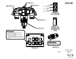
Page 17: ...Pitch Trim Controls Figure 5 OPERATING MANUAL 2A 27 00 Page 21 22 January 31 02 ...
Page 32: ...Rudder Pedals Forward Linkage Figure 13 OPERATING MANUAL 2A 27 00 Page 39 40 January 31 02 ...
Page 50: ...Flaps Simplified Block Diagram Figure 18 OPERATING MANUAL 2A 27 00 Page 61 62 January 31 02 ...


