•
NO GND SPOILERS light is extinguished
•
GND SPOILER warning message is not displayed on
CAS
•
Both MASTER WARN lights are extinguished
•
GND
SPOILER
UNARM
advisory
message
is
displayed on CAS
•
GND SPOILER light on SWLP (if installed) is
extinguished
(j) Retard the right power lever to idle. Verify the following
indications:
•
NO GND SPOILERS light is extinguished
•
GND SPOILER warning message is not displayed on
CAS
•
GND
SPOILER
UNARM
advisory
message
is
displayed on CAS
NOTE:
(1) When the power lever is advanced, the red GND
SPOILER
warning
message
may
be
displayed
momentarily and then extinguish. If the message
remains extinguished, continue the test.
(2) The absence of either the NO GND SPOILERS
light or the GND SPOILER message during Step 6 of
the ground spoiler system check, or any incorrect
indication, constitutes an unsuccessful ground spoiler
system check.
(3) The ground spoilers cannot always be observed
from the cockpit. The correct GND SPOILER message
and
NO
GND
SPOILERS
light
indications
are
sufficient
for
satisfactory
preflight
functional
verification.
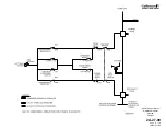
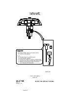
D. Flight Power Shutoff System:
The flight power shutoff valve is a mechanically operated shutoff valve
located between the Combined and Flight hydraulic system pressure
sources and the flight and ground spoiler actuator pressure lines. The
valve consists of two mechanically connected but hydraulically isolated
sections. A controlex cable connects the valve to a FLIGHT POWER SHUT
OFF handle located on the left aft side of the cockpit center pedestal. See
Figure 8.
Moving the FLIGHT POWER SHUT OFF handle up from its stowed
(horizontal) position to the vertical position mechanically closes the flight
power shutoff valve. With the valve closed, operating pressure is removed
from the spoiler actuators and use of the system is not possible.
In accordance with limitations established in the GIV Airplane Flight
Manual, pulling the FLIGHT POWER SHUTOFF handle with speed brakes
OPERATING MANUAL
PRODUCTION AIRCRAFT SYSTEMS
2A-27-00
Page 73
January 31/02
Revision 6
Summary of Contents for IV
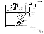
Page 17: ...Pitch Trim Controls Figure 5 OPERATING MANUAL 2A 27 00 Page 21 22 January 31 02 ...
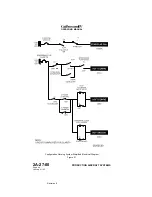
Page 32: ...Rudder Pedals Forward Linkage Figure 13 OPERATING MANUAL 2A 27 00 Page 39 40 January 31 02 ...
Page 50: ...Flaps Simplified Block Diagram Figure 18 OPERATING MANUAL 2A 27 00 Page 61 62 January 31 02 ...

