CAS Message:
Cause or Meaning:
MACH TRIM LIMIT
Elevator trim has reached electrical trim limit while
operating airplane in Mach Trim speed region (greater
than 0.80 Mach).
MACH TRIM OFF
PITCH TRIM switch selected OFF or electric pitch trim has
failed. (This message is inhibited at less than 0.82 Mach.)
STALL BARRIER 1-2
Stall barrier system giving stall angle indication.
STALL BARR 1-2 FAIL
Stall barrier failed.
It is normal for STALL BARR 1 FAIL message to be
displayed any time EMERGENCY FLAPS are used and
flaps position is greater than 22°.
STALL BARRIER OFF
STALL BARRIER switch is OFF or system not powered.
TRIM LIMIT
Autopilot elevator trim has reached electrical trim limits.
NOTE(S):
(1) CAA certified aircraft only.
Annunciation:
Cause or Meaning:
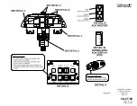
Amber chevron illuminated on pilot’s /
copilot’s AOA indexer.
AOA for approach and landing is too low.
4. Limitations:
A. Angle-of-Attack (AOA) System:
(1) Use As A Reference:
Angle-of-Attack (AOA) may be used as reference, but does not
replace airspeed as the primary reference.
(2) Indication Parameters:
AOA indication must be within white band once forward airspeed is
attained during takeoff roll.
(3) Use As A Speed Reference:
AOA shall not be used as a speed reference for takeoff rotation.
B. Stall Barrier / Stall Warning:
(1) Takeoff Requirements:
Both stall warning / stall barrier systems must be operative for
takeoff.
(2) Use of System:
Stall barrier systems must be ON during all flight operations except
as noted in Section 05-15-40, Stall Barrier Malfunction. Refer to this
system description for a description of the stall warning / stall barrier
system checkout procedure.
C. Mach Trim Compensation / Electric Elevator Trim:
(1) Use of mach trim compensation:
Mach trim compensation must be ON during all flight operations
except
as
provided
for
in
Section
05-03-40,
Mach
Trim
Compensation Failure.
(2) If mach trim compensation failure is coupled with yaw damper
failure:
When mach trim compensation failure is coupled with yaw damper
OPERATING MANUAL
PRODUCTION AIRCRAFT SYSTEMS
2A-27-00
Page 15
January 31/02
Revision 6
Summary of Contents for IV
Page 17: ...Pitch Trim Controls Figure 5 OPERATING MANUAL 2A 27 00 Page 21 22 January 31 02 ...
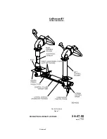
Page 32: ...Rudder Pedals Forward Linkage Figure 13 OPERATING MANUAL 2A 27 00 Page 39 40 January 31 02 ...
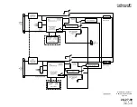
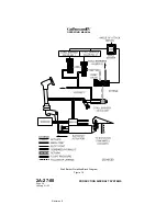
Page 50: ...Flaps Simplified Block Diagram Figure 18 OPERATING MANUAL 2A 27 00 Page 61 62 January 31 02 ...


