second warning function can occur both on the ground and in flight,
and is activated if there is a failure within the ground spoiler system
which might result in inadvertent spoiler extension. This is
annunciated by a red GND SPOILER warning message displayed
on CAS and, if installed, the SWLP.
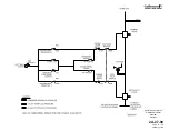
(2) Hydraulic Operation:
The ground spoiler system requires both control pressure and
operating pressure. Control pressure, also known as servo
pressure, is normally supplied by the Combined hydraulic system,
but can be supplied by either the Utility or Auxiliary hydraulic
systems. Operating pressure is supplied by the Combined and
Flight hydraulic systems. The ground spoiler system is solely a
hydraulically powered system, thus reversion to manual control is
not possible.
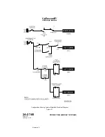
The ground spoiler hydraulic system contains primary and
secondary solenoid-operated hydraulic control valves located in the
main wheel well. Two ground spoiler actuators (one per side) are
located at the inboard ends of the left and right wing rear beam.
During normal operation, Combined and Flight hydraulic system
pressure is supplied through the open flight power shutoff valve to
the retract side of the ground spoiler actuators.
The ground spoiler automatic deployment feature is accomplished
by a common hydraulic signal that overrides any input to the servo
valve through the SPEED BRAKE handle. The override signal is
supplied by Combined (or Utility or Auxiliary) hydraulic pressure to
both actuators through normally-closed solenoid valves. Since the
override signal is common to both the left and right actuators, the
possibility of asymmetrical extension is virtually eliminated.
In the unlikely event that the ground spoilers inadvertently extend
during low-speed flight, the ground spoiler control system will extend
all six spoiler panels in unison to 55 +4/-3°. Should this occur at
higher airspeeds, the panels will “blow back” to an angle that
balances the aerodynamic load against the panels with the force
applied by the actuators.
If both Combined and Flight hydraulic system pressure is lost, a
bypass feature in the actuators allows the spoiler panels to “blow
down” to a trail position.
(3) Operational Logic:
The ground spoiler control system will automatically extend all six
spoiler panels in unison to 55 +4/-3° when the following parameters
are satisfied:
•
Main DC bus power is available to provide electrical power
for the system
•
Combined (or Utility or Auxiliary) hydraulic pressure is
available to provide servo pressure for spoiler control
•
Combined or Flight hydraulic pressure is available to provide
operational pressure to extend the spoilers
•
GND SPLR switch is selected to ARMED
OPERATING MANUAL
PRODUCTION AIRCRAFT SYSTEMS
2A-27-00
Page 70
January 31/02
Revision 6
Summary of Contents for IV
Page 17: ...Pitch Trim Controls Figure 5 OPERATING MANUAL 2A 27 00 Page 21 22 January 31 02 ...
Page 32: ...Rudder Pedals Forward Linkage Figure 13 OPERATING MANUAL 2A 27 00 Page 39 40 January 31 02 ...
Page 50: ...Flaps Simplified Block Diagram Figure 18 OPERATING MANUAL 2A 27 00 Page 61 62 January 31 02 ...

