2A-27-30: Yaw Flight Control System
1. General Description:
Aircraft movement about the vertical axis (yaw) is controlled by the position of a
single rudder. The rudder is both manually (rudder pedals) and electrically (yaw
damper) controlled, mechanically actuated and hydraulically boosted. It is
mounted on the trailing edge of the vertical stabilizer. Total rudder travel ranges
from 22° left or right of neutral.
The rudder is positioned by an electrohydraulic servoactuator located in the tail
compartment. The actuator receives hydraulic operating pressure simultaneously
from the Combined and Flight hydraulic systems during normal operations. In the
event of total loss of hydraulic pressure in both systems, the rudder reverts to
manual operation. Manual reversion is also possible through use of a flight power
shutoff valve and its pedestal-mounted control handle.
A rudder trim system is used to position the entire rudder surface (no trim tab is
incorporated). Manual trim is accomplished by a pedestal-mounted control knob.
A yaw damping system is incorporated to provide stability augmentation about the
vertical axis by counteracting any dutch roll tendency. Electrical inputs made by
the yaw damper to the rudder actuator are transparent to the flight crew and can
be made simultaneously with other inputs from the flight crew.
On CAA certified aircraft, a flight control automatic failure detection system
compares rudder pedal inputs to rudder actuator outputs. If a malfunction is
detected, the system shuts off either or both hydraulic power sources to the
actuator.
The yaw flight control system consists of the following subsystems, units and
components:
•
Rudder pedal system
•
Mechanical actuation system
•
Hydraulic boost system
•
Manual reversion system
•
Rudder load limiting system
•
Yaw damper system
•
Yaw trim system
•
Failure detection system (CAA aircraft only)
2. Description of Subsystems, Units and Components:
A. Rudder Pedal System:
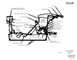
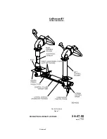
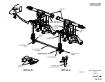
(See Figure 13.)
Each pair of rudder pedals functions both as a conventional rudder control
and toe brake control. With nosewheel steering operating, limited steering
control (7° left and right of neutral) is also available using the rudder
pedals.
Each pilot can adjust the resting position of their rudder pedals to enhance
comfort and usability. Lifting an adjusting lever located between each pair
of rudder pedals releases a lock to permit fore and aft adjustment. The
lever handle is then pulled aft or pushed forward, moving the rudder pedal
set in the same direction. Once in the desired position, releasing the lever
locks the pedals in place.
OPERATING MANUAL
PRODUCTION AIRCRAFT SYSTEMS
2A-27-00
Page 30
January 31/02
Revision 6
Summary of Contents for IV
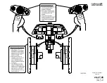
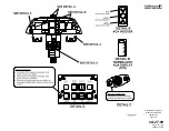
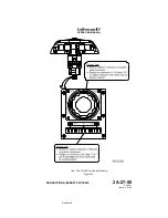
Page 17: ...Pitch Trim Controls Figure 5 OPERATING MANUAL 2A 27 00 Page 21 22 January 31 02 ...
Page 32: ...Rudder Pedals Forward Linkage Figure 13 OPERATING MANUAL 2A 27 00 Page 39 40 January 31 02 ...
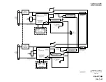
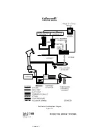
Page 50: ...Flaps Simplified Block Diagram Figure 18 OPERATING MANUAL 2A 27 00 Page 61 62 January 31 02 ...

