drops below 75 psi, bypass valves within the actuator open to allow the
actuator piston to idle. With the actuator piston idling, the system is said to
be in manual reversion, technically explained in the following paragraph.
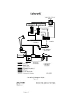
The input cable sector and output crank rotate on a mutually independent
common pivot. They are linked by a pin and elongated slot arrangement.
The input crank is on the pin and the output crank is on the slot. With the
actuator piston idling, the pin moves within the slot until it reaches either
end. At this point, mechanical contact is made and the input cable sector
now drives the output crank. The output crank, in turn, drives the rudder
through its push-pull rods and cranks.
Manual reversion of the yaw flight control system is also possible by
closing a normally open flight power shutoff valve. The flight power shutoff
valve is a mechanically operated shutoff valve located between the
Combined and Flight hydraulic system pressure sources and the rudder
actuator (as well as the aileron, elevator and flight / ground spoiler
actuator) pressure lines. The valve consists of two mechanically connected
but hydraulically isolated sections. A controlex cable connects the valve to
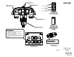
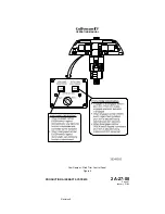
a FLIGHT POWER SHUT OFF handle located on the left aft side of the
cockpit center pedestal. See Figure 8.
Moving the FLIGHT POWER SHUT OFF handle up from its stowed
(horizontal) position to the vertical position mechanically closes the flight
power shutoff valve. With the valve closed, operating pressure is removed
from the actuator, allowing the piston to idle.
The resultant advantage of the flight power shutoff provision is the ability to
bypass a malfunctioning actuator (such as would be the need in the
unlikely event of an actuator jam) and manually fly the aircraft. Although
rudder pedal effort and response time to inputs are increased while in
manual reversion, the aircraft remains capable of positive and harmonious
control.
E. Rudder Load Limiting System:
(See Figure 12.)
Load-limiting (force-modulating) valves inside the rudder actuator restrict
Combined and Flight hydraulic system pressure to prevent vertical
stabilizer structural overload. Surface movement is limited by these valves
when higher airspeeds increase the airloads imposed against the rudder.
When the hinge moment limit is reached, the force-modulating shift,
reducing pressure to a maximum of approximately 2,250 psi, regardless of
hydraulic system pressure. Operation of either valve to restrict hydraulic
pressure closes an internal microswitch that triggers a blue RUDDER
LIMIT advisory CAS message. With the RUDDER LIMIT message
displayed, further displacement of the rudder surface is inhibited.
When on the ground with the Combined hydraulic system operating, rudder
actuator load limiting can be checked by applying gradual input force to the
rudder pedals until the rudder surface is bottomed against its stops (left or
right). The RUDDER LIMIT advisory CAS message will be displayed at the
instant of pressure limiting within the actuator. Flight crews are cautioned
that both the gust lock and nose wheel steering must be OFF before
performing this test. Also, it should be noted that if performing this test with
only the Flight hydraulic system operating, the RUDDER LIMIT message
may or may not be displayed.
OPERATING MANUAL
PRODUCTION AIRCRAFT SYSTEMS
2A-27-00
Page 32
January 31/02
Revision 6
Summary of Contents for IV
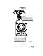
Page 17: ...Pitch Trim Controls Figure 5 OPERATING MANUAL 2A 27 00 Page 21 22 January 31 02 ...
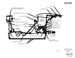
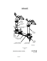
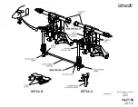
Page 32: ...Rudder Pedals Forward Linkage Figure 13 OPERATING MANUAL 2A 27 00 Page 39 40 January 31 02 ...
Page 50: ...Flaps Simplified Block Diagram Figure 18 OPERATING MANUAL 2A 27 00 Page 61 62 January 31 02 ...

