2A-27-50: Horizontal Stabilizer System
1. General Description:
A movable horizontal stabilizer provides automatic longitudinal trim assistance to
compensate for the nose pitchdown moment (tuck-in) associated with flap
extension. Stabilizer position (leading edge angle of incidence) is a direct function
of flap position, as the stabilizer is mechanically driven from the flap central
gearbox. If a malfunction occurs rendering the stabilizer immovable, a safe
landing can be made using normal pitch trim.
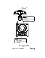
Horizontal stabilizer position is displayed on the FLAP / STAB position indicator
located on the copilot’s skirt panel.
The horizontal stabilizer system is composed of the following subsystems, units
and components:
•
Stabilizer drive system
•
Torque limiter
•
Dwell box
•
Stabilizer actuator
•
Stabilizer position and warning system
2. Description of Subsystems, Units and Components:
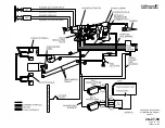
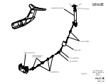
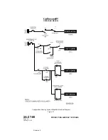
(See Figure 16 and Figure 17.)
A. Stabilizer Drive System:
The stabilizer drive system consists of torque shafts installed beginning
from the aft side of the flap central gearbox, rearward through the tail
compartment via a dwell box, then upward through the vertical stabilizer to
the stabilizer actuator. Bearing housings and pillow blocks installed at
defined intervals support the torque shafts, preventing whiplash as they
rotate.
B. Torque Limiter:
A torque limiter is installed at the input side of the central gearbox. If the
gearbox, dwell box or stabilizer actuator should jam or fail, the torque
limiter spring jams to lock the torque shafts. This stalls the central gearbox
hydraulic motor, stopping further flap and horizontal stabilizer movement.
If a torque shaft fails, the flaps are still operable throughout their full range.
The stabilizer, however, remains at its last position prior to shaft failure. The
flight crew would then use pitch trim as necessary to compensate for the
immovable stabilizer.
C. Dwell Box:
A dwell box, located in the tail compartment, is incorporated in the stabilizer
drivetrain to control stabilizer movement during flap extension and
retraction. It contains an input side and an output side.
During flap extension, the shaft connected to the input side of the dwell box
rotates but the output side does not rotate until the flaps reach a specified
position. At the final stages of central gearbox rotation, the shaft connected
to the output side of the dwell box rotates to drive the stabilizer actuator.
During flap retraction, the shaft connected to the output side of the dwell
box immediately begins rotation to drive the stabilizer actuator. When the
flaps reach a specified position, output shaft rotation ceases, although
OPERATING MANUAL
PRODUCTION AIRCRAFT SYSTEMS
2A-27-00
Page 49
January 31/02
Revision 6
Summary of Contents for IV
Page 17: ...Pitch Trim Controls Figure 5 OPERATING MANUAL 2A 27 00 Page 21 22 January 31 02 ...
Page 32: ...Rudder Pedals Forward Linkage Figure 13 OPERATING MANUAL 2A 27 00 Page 39 40 January 31 02 ...
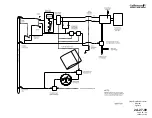
Page 50: ...Flaps Simplified Block Diagram Figure 18 OPERATING MANUAL 2A 27 00 Page 61 62 January 31 02 ...


