background image

GTC Sound Innovations REVPAD Manual

40

Tempo and Global Tempo

Some effects, such as DELAY and TREM (tremolo) include a 

TEMPO

 parameter that you set to anything from 30 to 300 beats per min-

ute.

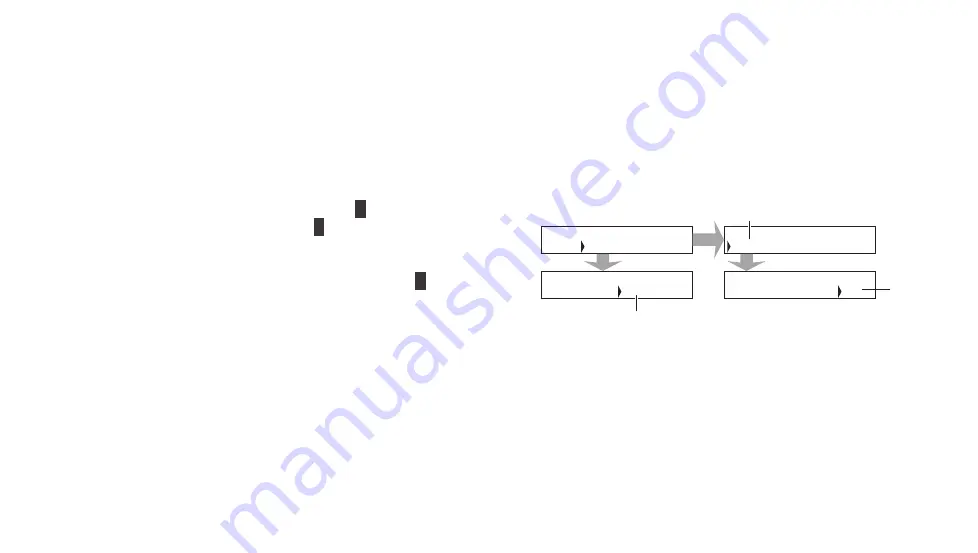
When you have a Patch that has more than one effect with tempo parameters you may want to make sure that they use the same 
tempo. Set a global tempo for the Patch as follows:

1.  Go to 

p3

 of the Patch and select PATCH ( 

A

 ).

2.  Navigate to the 

TEMPO

 parameter ( 

B

 ) and rotate the Navigation 

Roller to the tempo you want to use for all effects in the Patch.

3.  For each effect with a tempo parameter edit the 

TEMPO

 value by 

rotating the Navigation Roller until you see 

GLOB

 ( 

C

 ) so it will 

conform to the global tempo.

You can easily change the global tempo of the Patch by using Tap Tempo 
mode. 

See “Tap Tempo Mode” on page 50 for more information.

|PATCH|PAD  |MIDI |AUTO

|40   |30   |ON   |120

|LVL-L|LVL-R|FRZ  |TEMPO

3

P

01A: PATCH TO MODIFY

|DST-1|DELAY|TREM |SYMPH

|15   |14   |GLOB |1/4

|MIX  |T-MIX|TEMPO|SBDIV

1

P

01A: PATCH TO MODIFY

Summary of Contents for REVPAD

Page 1: ...SAVE SYS X Y X Y X Y X Y X Y B C BYPASS GTC Sound Innovations REVPAD Manual ...

Page 2: ...II REVPAD Firmware version 1 0 Last manual update 2017 02 10 ...

Page 3: ...nological copy protection measures This is due to the fact that this product is intended to be used for the purpose of producing original music and is therefore designed so that material that does not infringe copyrights belonging to others for example your own original works can be recorded or duplicated freely Do not use this unit for purposes that could infringe on a copyright held by a third p...

Page 4: ... Battery Safety Instructions 4 Battery Replacement Instructions 6 EMC and Certificate of Conformity 8 Quick Start 11 The REVPAD Touchpad 12 The REVPAD Base Unit 14 Take the REVPAD for a Spin 16 Exploring Your GTC Sound Innovations REVPAD 17 Getting to Know the REVPAD Base Unit 18 The Back Panel of the REVPAD Base Unit 26 Getting to Know the REVPAD Touchpad 31 Customizing your REVPAD 35 ...

Page 5: ...ix Touch Mix 39 Tempo and Global Tempo 40 Setting X Y Values in Effects 41 Saving a New Patch 43 Organizing Your Patch List 44 Modes 45 Patch Setup 51 Pad Setup 55 MIDI Setup 56 Auto Setup 57 External Control of Internal Effects 59 System Configuration 61 Device Utilities 61 Pad Settings 63 Touchpad Control Button Assignment 65 ...

Page 6: ... c Table of Contents MIDI Settings 68 MIDI IN CC Map 69 MIDI Control 71 MIDI IN 72 MIDI OUT 74 Specifications 79 MIDI Implementation Map 83 Contact Support 85 ...

Page 7: ...ve and includes the possibility to change effects while playing The REVPAD includes multiple Patches presets of effect parameters including analog distortion and overdrive as well as additional effects such as chorus delays and virtual faders It enables the user to manipulate sound effects by swiping or tapping the Touchpad surface and allows for improvisation and creating new effects on the fly T...

Page 8: ... only with a dry cloth Do not use any chemicals This equipment has been tested and found to comply with the limits for a Class B digital device pursuant to Part 15 of the FCC rules See EMC and Certificate of Conformity on page 8 for more information Warning DO NOT INGEST BATTERY CHEMICAL BURN HAZARD This product contains a coin button cell battery If the coin button cell battery is swallowed it ca...

Page 9: ... the power cord from being walked on or pinched The DC power jack is used to disconnect the REVPAD Please keep this plug accessible Charge the REVPAD Touchpad frequently this will increase the lifetime of the battery In long storage periods it is recommended to remove the battery from the REVPAD Touchpad Limit exposure to extremely high noise levels Charge the REVPAD Touchpad with the USB cable su...

Page 10: ...eterioration of performance or failure See Battery Replacement Instructions on page 6 before installing or removing the battery from the REVPAD Touchpad All of the following are dangerous Do not leave charge or use the battery in a car or similar place where inside temperature might be over 60º C 140 F Do not leave the battery near a fire or a heat source Do not throw the battery into a fire Do no...

Page 11: ...inue charging process Immediately disconnect the battery and observe it in a safe place for approximately 15 minutes If at any time leakage or foul odors are detected make sure that there is sufficient distance from fire If liquid leaking from the battery gets onto your skin or clothes immediately wash well with fresh water If liquid leaking from the battery gets into your eyes do not rub them Imm...

Page 12: ...HEMICAL BURN HAZARD This product contains a coin button cell battery If the coin button cell battery is swallowed it can cause severe internal burns in just two hours and can lead to death Keep new and used batteries away from children If the battery compartment does not close securely stop using the product and keep it away from children If you think batteries might have been swallowed or placed ...

Page 13: ...horized collection site for recycling waste electrical and electronic equipment If recycling is not available in your community the battery should be disposed of responsibly according to local codes 6 Clean the leads of the new battery 7 Replace the battery into the holder in the correct orientation Note Make sure that you place the battery as is pictured in the illustration A battery placed the w...

Page 14: ...nce with the instructions may cause harmful interference to radio communications However there is no guarantee that interference will not occur in a particular instal lation If this equipment does cause harmful interference to radio or television reception which can be determined by turning the equipment off and on the user is encouraged to try to correct the interference by one or more of the fol...

Page 15: ...arby persons Per 2 1091d d 4 In some cases for example modular or desktop transmitters the potential conditions of use of a device may not allow easy clas sification of that device as either Mobile or Portable In these cases applicants are responsible for determining minimum distances for compliance for the intended use and installation of the device based on evaluation of either specific absorpti...

Page 16: ...GTC Sound Innovations REVPAD Manual 10 ...

Page 17: ... can be simultaneously assigned to any axis on the pad and by that to actually perform as virtual faders and switches for any aspect of the signal and its processing It gives the player full accurate and super dynamic control of the effects with just a simple finger tap touch or swipe It also eliminates the need to go to the pedal board to change effects and the hassle of bending down and tweaking...

Page 18: ...op fastener dots which stick onto the guitar body in any location according to your personal preference It is easily removed if it needs to be replaced The Touchpad attaches to the dots firmly enough to endure even the most vigorous live performance while remaining easy to remove The guitar remains clean and undamaged Note The hook loop fastener dots may leave marks on vintage guitars with nitroce...

Page 19: ...arged See Charging the REVPAD Touchpad on page 34 for more information 3 Remove one side of the adhesive backing of a hook loop fastener dot 4 Press the adhesive firmly in the recessed circle on the inside face of the Touchpad Repeat with the second hook loop fastener dot 5 Remove the adhesive backing of both hook loop fastener dots 6 Attach the Touchpad to your guitar where you can conveniently t...

Page 20: ...to and feel of the guitar player s fingers The REVPAD System offers 200 factory and user presets to build and explore your own sounds Building a Patch is easy and intuitive Step 1 Choose any effect you want Step 2 Explore the effect to set parameters Step 3 Push a button to select which one of those parameters you d like to be controlled by the Touchpad and in which direction X X Y Y Repeat those ...

Page 21: ... 9 VDC transformer to the POWER inlet on the base unit back panel 2 Run a guitar cable from your electric guitar to the INPUT connector 3 Run a guitar cable from the OUTPUT LEFT connector on the REVPAD Base Unit to your amplifier Note The REVPAD system accommodates a wide range of output options See Connecting Your REVPAD to the Outside World on page 28 for more information 4 Connect the antenna t...

Page 22: ...s any of the three Touchpad Control Buttons E The default Bank and Patch will appear in the Active Patch Screen C Now experiment and explore Tap the Touchpad F or slide your finger along the X or Y axis as you play Scroll through all of the Patches by rotating the Navigation Roller D or Bank by Bank by pressing Next Bank G footswitch C and D together or Previous Bank H footswitch A and B together ...

Page 23: ...ossibility to change effects while playing The REVPAD includes multiple Patches presets of effect parameters including analog distortion and overdrive as well as additional effects such as chorus delays and virtual faders It enables the user to manipulate sound effects by swiping or tapping the Touchpad surface and allows for improvisation and creating new effects on the fly The REVPAD enables smo...

Page 24: ...Manual 18 Getting to Know the REVPAD Base Unit The REVPAD Base Unit is used to for electronic connections status of the system editing Patches and modifying effects The Front Panel of the REVPAD Base Unit REVPAD Base Unit Controls ...

Page 25: ... on page 49 for more information Patch Lights when the REVPAD is in Patch Favorite mode See Patch Favorite Mode on page 47 for more information Normal Lights when the REVPAD is in Normal mode See Normal Mode on page 46 for more information C Navigation Roller Arrows above below to the left and to the right of the Navigation Roller knob are used for navigating between screens Above each arrow a LED...

Page 26: ... user can decide if a given effect such as volume is controlled by the X or Y axis on the Touchpad See Setting X Y Values in Effects on page 41 for more information F SYS Button Use this button to access the System Preferences screen See System Configuration on page 61 for more information G Footswitches The footswitches A B C and D are used to scroll through Banks of Patches change Patches within...

Page 27: ...D makes 200 Patches available stored in 50 Banks each of which with four Patch es The Current Bank Screen shows which Bank is active 01 through 50 The LEDs above the footswitches G show which of the four Patches in the Bank A B C or D is active The full Patch ID also appears in the Editing Screen A ...

Page 28: ...AD Manual 22 Status and Mode LEDs This section describes the meaning of the LED indicators on the front panel of the REVPAD base unit SAVE SYS X Y X Y X Y X Y X Y A B C D BYPASS SET 1 2 3 CLIP COMM BATT FREEZE PEDAL PATCH NORMAL ...

Page 29: ...h the base unit Yellow Weak communication with the base unit Information from the Touchpad is not fully transmitted to the base unit Red Bad communication with the base unit Most of the information from the Touchpad does not reach the base unit A weak signal can result from the following causes The distance from the base unit is too great There is a physical barrier such as a wall between the REVP...

Page 30: ...ion E PEDAL Green LED indicates that the REVPAD is operating in Single mode See Single Mode on page 49 for more information F PATCH Indicates that the REVPAD is working in Patch Favorite mode See Patch Favorite Mode on page 47 for more information G NORMAL Green LED indicates that the REVPAD is operating in Normal mode See Normal Mode on page 46 for more information Note Single Patch and Normal mo...

Page 31: ... REVPAD from the current Bank to the next Bank down for example from 21 to 20 The selected Bank number will flash Press one of the footswitch pedals to select one of the four Patches in the Bank Press footswitches C and D simultaneously E to move the REVPAD from the current Bank to the next Bank up for example from 21 to 22 The selected Bank number will flash Press one of the footswitch pedals to ...

Page 32: ...GTC Sound Innovations REVPAD Manual 26 The Back Panel of the REVPAD Base Unit This section describes the controls and sockets on the back panel of the REVPAD base unit ...

Page 33: ...DI IN MIDI IN socket to receive commands for control change program change and clock tempo changes See MIDI Control on page 71 for more information G MIDI OUT THRU MIDI OUT and or MIDI THRU socket See MIDI Control on page 71 for more information H OUTPUT LEFT Main audio output I OUTPUT RIGHT Secondary audio output J AMP MIX For switching the output source amplifier or mixer direct output K POWER 9...

Page 34: ... The AMP LINE switch should be set to AMP REVPAD to Two Amplifiers 1 Connect the REVPAD Output L in to the main amp input 2 Connect the REVPAD Output R in to the secondary amp input 3 Make sure the amplifier switch is on REVPAD Loop and Expression to External Audio Devices Follow the diagram to use the REVPAD Loop and Expression to add external audio devices Note The LOOP effect must be on for thi...

Page 35: ...e and after the amplifier s pre amp using a combination of the REVPAD and amp loops You must use the LOOP effect in the REVPAD Effects before the LOOP in the REVPAD will be processed before the amplifier pre amp Effects that will be after the LOOP in the REVPAD will be processed after the amplifier s pre amp REVPAD Guitar Input AMP Out L SND RTN In RTN SND REVPAD Guitar Input AMP Out L SND RTN In ...

Page 36: ...to your REVPAD REVPAD to Line or Mixer Use this configuration to connect the output of the REVPAD to one or multiple lines or mixers The AMP LINE switch should be set to LINE REVPAD AMP Guitar Input Out L Input MIDI Device MIDI Out MIDI In MIDI In MIDI Out REVPAD Line Direct Guitar Input Out L Input Line Direct Out R Input ...

Page 37: ...d combine this naturally with playing the guitar Up to eight effects and their parameters can be simultaneously assigned to any axis on the pad and by that to actually perform as virtual faders and switches for any aspect of the signal and its processing It gives the player full accurate and super dynamic control of the effects with just a simple finger tap touch or swipe It also eliminates the ne...

Page 38: ...GTC Sound Innovations REVPAD Manual 32 Item Name Function A Control Button 1 Touchpad Control Button 1 See Touchpad Control Button Assignment on page 65 for more information ...

Page 39: ...munication with the base unit thus bypassing the antenna Wait for PAD CONNECTED to appear in the base unit display area before using the Touchpad If this is the first time you are using the Touchpad the mes sage will say PAD WAS SUCCESFLLY ASSIGNED G H Hook loop fastener area Back view See Attaching the Touchpad on page 12 for more information I Battery Housing Cover Back view Remove this cover to...

Page 40: ...d with the USB cable when playing off stage at home or in a recording studio To recharge the REVPAD Touchpad 1 Make sure that the base unit is connected to an electrical source via the power supply 2 Attach the micro USB end of the cable to the Touchpad 3 Connect the other end to the base unit 4 Wait for PAD CONNECTED to appear in the base unit display area before touching the Touchpad If this is ...

Page 41: ...s Building a Patch is easy and intuitive Step 1 Choose any effect you want Step 2 Explore the effect to set parameters Step 3 Push a button to select which one of those parameters you d like to be controlled by the Touchpad and in which direction X X Y Y Repeat those three action steps to all of the other effects you d like to add to the effect chain and press the save button That s all you need t...

Page 42: ... Navigation Roller A to scroll through Patches B until you see a blank editing screen C The down arrow will glow yellow D 2 Press E on the Navigation Roller to enter the first effect block F Note The Up Right and Down arrows now glow indicating available navigation directions 3 Rotate the Navigation Roller G to scroll through the list of available effects until you find one you wish to add to the ...

Page 43: ...s the right arrow B until the cursor stands on the existing effect you need to move in order to make room for a new effect Rotate the Navigation Roller A until Ins appears C It flashes three times Continue with adding the effect See Creating and Editing Patches on page 36 for more information To delete an effect in a Patch press the right arrow B until the cursor stands on the existing effect you ...

Page 44: ...te the Navigation Roller C until the desired value appears 2 Press the right arrow B once more to enter page two of the parameter screens E 3 When you have finished adjusting these parameters press the up arrow G to return to the effects screen G 4 To add a delay effect to this Patch press the right arrow B and rotate the Navigation Roller clockwise C until the DELAY effect appears As before press...

Page 45: ... the Patch It determines how much of the effect will be heard in the global Patch mix T MIX determines the mix of the effect while the user is touching the Touchpad The T MIX parameter overrides the normal MIX parameter Note The MIX parameter cannot be assigned to an X Y Touchpad control The T MIX param eter can be assigned to an X Y Touchpad control In Freeze Mode only T MIX is active ...

Page 46: ...nd select PATCH A 2 Navigate to the TEMPO parameter B and rotate the Navigation Roller to the tempo you want to use for all effects in the Patch 3 For each effect with a tempo parameter edit the TEMPO value by rotating the Navigation Roller until you see GLOB C so it will conform to the global tempo You can easily change the global tempo of the Patch by using Tap Tempo mode See Tap Tempo Mode on p...

Page 47: ...th the Touchpad When you remove your finger it goes back to the default maximum Note You cannot change an effect parameter s minimum value When in Freeze mode the value will stay on the point the value attained after removing the finger from the Touchpad When there is no contact with the Touchpad an effect parameter will revert to its predefined maximum value even after being sur passed during con...

Page 48: ... the RANGE parameter Rotate the Navigation Roller A to change the range to 70 6 Press the X Y button D Each press changes the axis and direction as seen in the arrow by the range value A fifth press to the button removes the X Y value The color of the X or Y LED E under the parameter indicates X LED red The effect is controlled by the X axis X LED green The effect is controlled by the X axis Y LED...

Page 49: ...letter or number of the name you want to give this new Patch appears 3 Press the right arrow E to continue adding to the name Press twice to insert a space between words 4 When you have completed writing the name for the Patch press the down arrow F and then SAVE G Press the SAVE button once more to confirm the operation Note You can cancel the save process at any time by pressing the HOME button ...

Page 50: ...reating your own Patches you can use them to move existing Patches in order to make space This example shows how to move Patch 01A to make room for a new Patch created in slot 25B 1 Select Patch 01A and press the SAVE button 2 Change the Patch number to a currently blank spot 40B and press the SAVE button again Note Saving a new or modified Patch to an existing Patch number will overwrite the orig...

Page 51: ...REVPAD can be operated in different work modes which change the way the Touchpad controls the base unit The modes are True Bypass Mode Normal Mode Freeze Mode a selected function of Normal Mode Patch Favorite Mode Single Mode Tap Tempo Mode ...

Page 52: ...byPASS 3 Press the assigned Control Button or Control Button pair again to toggle back to the previously active Patch Normal Mode The basic way to work with your REVPAD system is in Normal mode In Normal mode the guitarist can control effect parameters and even make changes to them on the fly while playing the guitar When Normal mode is active the Normal LED on the base unit front panel is illumin...

Page 53: ...g to set Freeze mode on or off See Patch Setup on page 51 for more information Patch Favorite Mode See Setting Patch Favorites on page 48 for instructions on how to create sets of Patches you can access by pressing a Touchpad Control Button or Control Button pair and then tapping a specified area of the Touchpad When Patch Favorite mode is active the Patch LED on the base unit front panel is illum...

Page 54: ...en and select one of two options Select Only After pressing a Touchpad segment to activate the assigned Patch the editing screen on the base unit continues to display the Patch Favorite set You may play using the selected Patch but pressing the Touchpad will change the Patch Press the Touchpad Control Button again to remove the display Select and Play makes the Patch selection immediately upon tou...

Page 55: ...d Control Button and then tapping regions of the Touchpad Follow the procedure below to set up REVPAD system to use Single mode 1 Assign Single to a Control Button or Control Button pair on the Touchpad See Touchpad Control Button Assignment on page 65 for more information 2 Each Touchpad segment is automatically assigned to the first six effects in the active Patch Activate Single mode by pressin...

Page 56: ...r more information Note Because you will be looking at the Touchpad from above when it is attached to your guitar the illustration shows the guitar ist eye view Follow the procedure below to initiate Tap Tempo mode 1 Assign Tap to a Control Button or Control Button pair on the Touchpad See Touchpad Control Button Assignment on page 65 for more information 2 Activate Tap Tempo mode by pressing the ...

Page 57: ...the down arrow button on the Navigation Roller 4 See the table below for an explanation of the settings in this and the next screen Item Name Value Notes A LVL L LVL R 0 through 100 Level through left and right outputs B FRZ OFF ON See Freeze Mode on page 46 for more information C TEMPO 30 through 300 Global Patch tempo See Tempo and Global Tempo on page 40 for more information D ROUT SER See Rout...

Page 58: ...effects until the end of the signal chain to the output BYPASS The signal bypasses all the effects and goes directly to the output FX1 The signal outputs after FX1 FX2 The signal outputs after FX2 FX3 The signal outputs after FX3 FX4 The signal outputs after FX4 PAGE1 The signal outputs after FX1 through FX4 FX5 The signal outputs after FX5 FX6 The signal outputs after FX6 FX7 The signal outputs a...

Page 59: ...ess the down arrow button on the Navigation Roller 4 Press the right arrow button on the Navigation Roller to Routing options A on page two Turn the Navigation Roller to select one of the six routing options Note FX1 through FX4 are the four effects on p1 FX5 through FX 8 are the four effects on p2 SER Serial Serial SER processes all effects one after the other COMB1 Combination One Combination On...

Page 60: ... in parallel COMB3 Combination Three Combination Three COMB3 processes all p1 effects FX1 through FX4 in parallel and then all p2 effects FX5 through FX8 serially COMB4 Combination Four Combination Four COMB4 processes all p1 effects FX1 through FX4 in parallel and then all p2 effects FX5 through FX8 in parallel PAR Parallel Parallel PAR processes all effects in parallel ...

Page 61: ...et for values between 0 and 100 Using the Pad setup screen you can set minimum and maximum values for the borders to other values 1 Select a Patch for setup See Creating and Editing Patches on page 36 for more information 2 Go to p3 3 With PAD selected press the down arrow button on the Navigation Roller 4 See the table below for an explanation of the settings ...

Page 62: ...m border of the y axis MIDI Setup Go to p3 of a selected Patch editing screen to access the MIDI setup parameters 1 Select a Patch for MIDI setup See Creating and Editing Patches on page 36 for more information 2 Go to p3 3 With MIDI selected press the down arrow button on the Navigation Roller 4 See MIDI OUT Control Change on page 75 for information about the first options A B and C See MIDI Cloc...

Page 63: ...r setup See Modifying a Patch on page 37 for more information 2 Go to p3 3 With AUTO selected press the down arrow button on the Navigation Roller 4 See the table below for an explanation of the settings of the ADSR and LFO options Note Only one of these options can be active at the same time If LFO is chosen ADSR is disabled Likewise if ADSR is chosen LFO is disabled ADSR Options A Name Value Not...

Page 64: ...ulation holds the maximum value T DN Determines the time for the movement to go from the maximum to minimum value HOLD2 Determines how long the simulation holds the minimum value LFO Options B Name Value Notes LFO X Y XY Z OFF Choose the direction the simulation will work MIN 0 The minimum value of the movement where the movement begins MAX 0 to 100 The maximum value of the movement where the move...

Page 65: ...ut jack connect the REVPAD s EXP PEDAL socket C to the expression pedal input of the external device The MIX and T MIX parameters are used to control the mix of the external audio devices that run through the loop connections The RANGE AUTO and TIME parameters are used to control the ex pression signal coming from an external device with the REVPAD RANGE determines the maximum range of the express...

Page 66: ...GTC Sound Innovations REVPAD Manual 60 ...

Page 67: ... the SYS button to view DEVICE UTILITIES Press the right button on the Navigation Roller to see the next screen Pad Set tings Press the down button on the Navigation Roller to view and modify REVPAD device utilities Rotate the Navigation Roller to scroll through your options in each configuration field Press the right arrow to continue to the next configuration field Press the up arrow to return t...

Page 68: ...he RF value connect the Touchpad to the base unit with the USB cable Then turn the Touchpad off and on again to reset the unit calibration Wait for PAD CONNECTED to appear in the base unit display area before using the Touchpad 1 5 DI_BOX Off Set this parameter to On or Off to globally enable or disable all the DIBOX effect in all Patches If it is set to Off the DIBOX effect will not work even if ...

Page 69: ...e next configuration field Press the up arrow to return to the main System Configuration Screen Number Name Values Notes 2 1 PAD SPLITS 2 Segments 4 Segments 6 Segments The Touchpad can be split into 2 4 or 6 segments for use in Patch Favorite mode and for MIDI Control Each segment can be assigned to various functions See Touchpad Control Button Assignment on page 65 for more information 2 2 FAVOR...

Page 70: ... on The base unit displays the first six effects of the active Patch The effects remain visible so you may bypass other effects or turn bypassed effects back on Select and Play Press the Touchpad Control Button or Control Button pair assigned to Single mode Then tap the Touchpad to bypass the effect assigned to that particular segment Once you have tapped an effect you exit Single mode 2 4 PADS EN...

Page 71: ...d from above when it is attached to your guitar the illustration shows the guitar ist eye view 1 Press the down button of the Navigation Roller to view and modify your REVPAD Touchpad Control Button assignments 2 To change the present assignment for SW1 Touchpad Control Button 1 rotate the Navigation Roller to scroll through your options See table below for a list of all options 3 Press the right ...

Page 72: ...6 for more infor mation Up Scrolls up to the next higher Patch Down Scrolls down to the next lower Patch BnkUp Scrolls up to the next higher Bank Then press one of the footswitches to select the A B C or D Patch from that Bank BnkDn Scrolls down to the next lower Bank Then press one of the footswitches to select the A B C or D Patch from that Bank Tap Toggles Tap Tempo mode on or off See Tap Tempo...

Page 73: ...PC 2 and normal mode MPC 3 Toggles between MIDI Program Change 3 MPC 3 and normal mode Byp Toggles Bypass mode on and off F S A Changes to Patch A in an active Bank F S B Changes to Patch B in an active Bank F S C Changes to Patch C in an active Bank F S D Changes to Patch D in an active Bank ...

Page 74: ...PAD MIDI settings Rotate the Navigation Roller to scroll through your options in each configuration field Press the right arrow to continue to the next configuration field Press the up arrow to return to the main System Configuration Screen Number Name Values Notes 4 1 PC TX CHANNEL Off 1 to 16 The MIDI channel on which the REVPAD sends program change messag es 4 2 PC TX FUNCTION Select Only Selec...

Page 75: ...the REVPAD MIDI IN Control Change CC map MIDI Control Change messages can be used to turn a particular effect within the current Patch on or off Use the right arrow button on the Navigation Roller to scroll through all effects that can be controlled using MIDI IN Control Change messages When the cursor stands on a particular effect use the Navigation Roller to select the MIDI IN channel 1 to 16 tu...

Page 76: ...GTC Sound Innovations REVPAD Manual 70 ...

Page 77: ...nect a cable from the MIDI OUT THRU port B in the back panel of your REVPAD Base Unit to the MIDI in port of your MIDI Device Set up communication between your MIDI device and your REVPAD system as follows 1 Press the SYS button C three times You will see the MIDI SETTINGS menu D 2 To set the MIDI OUT channel press the down arrow E The default program change transmit PC TX channel F will be shown ...

Page 78: ...ange messages allows you to use your MIDI device to change the active REVPAD Patch 1 Connect a cable from the MIDI OUT port of your MIDI device to the MIDI IN connector in the back panel of the base unit Make sure that the MIDI receive channel RX is set to the channel the other MIDI device is sending on See MIDI Control on page 71 for more information 2 When a program change command is sent from a...
Page 79: ...B 3 Press the down arrow C to see the CC Map D The first effect Distortion 1 DST 1 is selected with the default value of Off 4 Use the Navigation Roller E to select the Control Change value from 0 to 127 of the external MIDI controller that you want to use to turn on and off bypass the selected effect in the current REVPAD Patch Note If you do not know the Control Change value sent by a controller...

Page 80: ... the guitar ist eye view 1 Connect the MIDI OUT THRU port on the back panel of the REVPAD base unit to the MIDI IN port of your MIDI device using a standard MIDI cable Make sure that the MIDI TX channel on the REVPAD and the MIDI Receive channel on your MIDI device are set to the same channel See MIDI Control on page 71 for more information 2 Choose the number of segments you wish to make active o...

Page 81: ...e messages allows you to use the Touchpad to send up to six different CC values to external MIDI devices 1 Connect the MIDI OUT THRU port on the back panel of the REVPAD base unit to the MIDI IN port of your MIDI device using a standard MIDI cable Make sure that the MIDI TX channel on the REVPAD and the MIDI Receive channel on your MIDI device are set to the same channel See MIDI Control on page 7...

Page 82: ...DI channel has two control change screens UTCH 0 to 127 Value sent when the user lifts his fingers from the Touchpad Untouch HOLD Cancels the Untouch value If set to Hold lifting the finger from the Touch pad will not send another value for this Continu ous Controller TCH 0 to 127 Value sent when the Touchpad is touched See Setting X Y Values in Effects on page 41 for more information MIN 0 to 127...

Page 83: ...etting MIDI CLOCK messages received by the REVPAD from an external MIDI device will change the global tempo of the current Patch to the received clock Sending MIDI Clock messages from REVPAD You can send the global tempo of the current Patch as Clock messages to an external MIDI device Changing the global tempo of the Patch will change the outgoing Clock messages as well To set up your REVPAD as t...

Page 84: ...GTC Sound Innovations REVPAD Manual 78 ...

Page 85: ... configurations X Y button for quick effect parameters assignment and their directions to the Touchpad s X Y axis Four footswitches for switching to true bypass or between Patches Eight LED indicators Output Master Level Control Knob Touchpad Wireless assignable X Y Z pad controller and sound shaper Three assignable buttons for control operational modes External Interface Instrument Input Connecti...

Page 86: ...e PC connection for firmware updates and user downloads Connection USB 2 0 type B USB PAD Purpose Touchpad association Touchpad battery charging and wired communication Connection USB 2 0 type A Pedal Exp and Vol Purpose Control external units with expression pedal input Connection stereo phone jack Audio Specifications Sample Rate 44 1 kHz A to D Conversion 24 bit D to A Conversion 24 bit True by...

Page 87: ...torage Temperature 20 to 70 C 4 to 158 F Operating Temperature 0 to 40 C 32 to 104 F Power Requirements Base Unit Transformer Main Voltage 100 to 240 VAC 50 60 Hz DC input 9 VDC input 2000 mA Power consumption 18W Power Requirements Touchpad DC input 5 VDC through USB connection Mechanical Specifications Base Unit Dimensions 290 x 167 x 70 mm 11 4 x 6 6 x 2 8 ...

Page 88: ...2 Weight 1 2 kg 2 7 lb Touchpad Dimensions 122 x 44 x 8 mm 4 8 x 1 73 x 0 32 Weight 45 gm 0 1 lb Attachment mechanism 3M double side scotch Note Due to continuous development these specifications are subject to change without prior notice ...

Page 89: ...cognized Remarks Basic Channel Default 1 1 Changed 1 to 16 1 to 16 Mode Default X X Messaged X X Altered X X Note number X X True Voice X X Velocity Note ON X X Note OFF X X After touch Key X X Channel X X Pitch bend X X X X Control change 0 to 127 0 to 127 Program change O O ...

Page 90: ...ion Transmitted Recognized Remarks True 0 to 127 0 to 127 System exclusive X X Common Song pos X X Song sel X X Tune X X System Real time Clock O O Commands X X Aux Messages Local ON OFF X X All notes OFF X X Active sense X X Reset X X O Yes X No ...

Page 91: ...product home page gtcsound com product revpad REVPAD FAQ gtcsound com faq GTC Sound Innovations Social media GTC Sound Innovations on Facebook facebook com gtcrevpad Contact Address GTC Sound Innovations P O Box 10567 Haifa 2611701 Israel E Mail odede gtcsound com Phone 972 52 8472255 ...

Reviews: