GSi Autoflow 2000 Series Instruction Manual Download Page 26

2000  Autoflow

26

INSTALLATION

Drying Chamber Low-Level Rotary Switch Installation

     1)

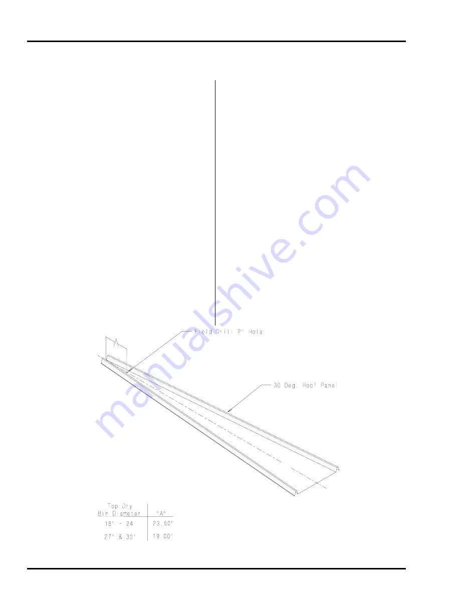
Drill a  2” diameter hole through the
roof panel at the location shown in
figure 8.
See component placement on
page 9 for proper placement in

              relation to fill auger.

     2)

Use the mounting plate as a pattern and

              drill four 3/8” holes through the roof

panel at the switch location so the plate

             can be bolted to the roof.

     3)

Attach the flex coupling to the rotary
switch power pack using a roll pin.

     4)

Apply teflon tape or pipe sealant (not
included) to the rotary switch power
pak threads and thread the rotary
switch power pack into the mounting
plate coupling.

     5)  Make sure that the conduit hole is at

     6)

Caulk the underside of the mounting
plate and on all sides of the 2” hole.

     7)

Bolt the assembly to the roof panel.

     8)

Attach the shaft extension according to

             figure 9.

     9)

Apply teflon tape or pipe sealant (not
included) to the shaft guard.

    10) Thread to underneath side of mounting
              plate.

    11) Add the 1/4” drilled coupling to the

shaft extension using the cotter pin.

    12) Attach the 1-vane paddle to the flex

coupling as shown in figure 9.

right angles with the roof panel ribs or

             facing towards the eave.

Figure  8

Summary of Contents for Autoflow 2000 Series

Page 1: ...2000 Autoflow 1 1 Series2000Autoflow Fan HeaterandControl Installation Instructions I n s t a l l a t i o n Manual PNEG 900 PNEG 900...

Page 2: ...ce iwth the current INSTALLATION CODES FOR GASBURNINGAPPLICANCESANDEQUIPMENT CAN1_B149 1andB149 2 orapplicable provincial regulations which should be carefully followed in all cases Authorities having...

Page 3: ...ng Chamber High Level Rotary Switch Installation 28 Drying Chamber Overflow Switch Installation 30 LPFuelSpecificationsandRecommendations 32 NGFuelSpecificationsandRecommendations 33 cuit Runs 34 Elec...

Page 4: ...IONS CAN CAUSE AIR EXHAUST OR INTAKE PORTS TO FREEZE Thank you for choosing a Top Dry Series 2000 Autoflow unit It is designed to give excellent per formance and service for many years This manual des...

Page 5: ...and understood by all people in the grain handling area The ro tating blade fire warning decals and voltage danger decal must be displayed on the fan can The bot tom right decal should be present on t...

Page 6: ...of the product This product has sharp edges These sharp edges may cause serious injury To avoid injury handle sharp edges with caution and use proper protective clothing and equipment at all times Gua...

Page 7: ..._________________________________________________________________________________________ ______________________________________________________________________________________________________________...

Page 8: ...11 Eave Height 18 5 22 1 25 9 29 5 33 1 36 9 40 5 Autoflow Control Box Mounting 1 The Autoflow Control Box should be mounted at eye level Make sure to mount the Autoflow control box so that the fan an...

Page 9: ...2000 Autoflow 9 Component Placement INSTALLATION...

Page 10: ...2000 Autoflow 10 Series 2000 Autoflow Control Box Bolt Pattern Figure 1 Illustration of the bolt pattern for the Autoflow control box INSTALLATION...

Page 11: ...erconnecttheFill SystemControlBox withtheAutoflow Control Box and thatpowerwireswill have to be run from the entrance panel to theFill System control Box to power theFill System and Aerationfanmotors...

Page 12: ...2000 Autoflow 12 CONTROLBOXMOUNTING Fill System Control Box Mounting Figure 2 Fill System Control Box Bolt Pattern...

Page 13: ...at a 110V power supply willneedtorun from the entrance panel to theActuatorControlBox to power the 24V DC battery charger 4 Use the pattern in Figure 3 to drill holes for the Actuator Control Box 5 If...

Page 14: ...2000 Autoflow 14 CONTROLBOXMOUNTING Actuator Control Box Mounting Figure 3 Bolt pattern to drill holes for the Actuator Control Box...

Page 15: ...is 10 1 2 above the floor sheet rib on all temperature sensor brackets to exit the dry ing chamber at the same place 6 Run the cords into the junction box after the junc tion box has been mounted to...

Page 16: ...2000 Autoflow 16 INSTALLATION Figure 5 Illustration of grain temperature sensor mounted on outside leveling band post Grain Temperature Sensor Mounted to Leveling Band Post...

Page 17: ...2000 Autoflow 17 INSTALLATION Close Up Detail of Grain Temperture Sensor Wiring...

Page 18: ...valley on the bin sidewall 2 Insert the probe through the 3 4 hole 3 Position the housing so the cord exits the housing horizontally and the tabs fall on the sidewall peaks 4 Use two self drilling scr...

Page 19: ...2000 Autoflow 19 Plenum hi limit installation INSTALLATION...

Page 20: ...fan entrance Do not install between two fan entrances 4 Mark bin wall where conduit will pass through and drill a hole just large enough to allow the conduit to pass through Seal this with caulking wh...

Page 21: ...mounting plate as a pattern anddrillfour3 8 holesthroughthe sidewallattheswichlocationsothe place can be bolted to the bin 5 Add foam weather strip around the top and side of the mounting plate 6 Caul...

Page 22: ...2000 Autoflow 22 INSTALLATION Figure 6...

Page 23: ...can be bolted to the bin 5 Add foam weather strip around the top and side of the mounting plate 6 Caulktheundersideofthemounting plate on all sides of the 2 hole and where the plate meets the bin 7 B...

Page 24: ...2000 Autoflow 24 INSTALLATION Figure 7...

Page 25: ...The Drying Chamber Rotary Switches should be located in close proximity to one another to lessen the amount of conduit and wiring required The rotary switches should also be mounted so that they are...

Page 26: ...pply teflon tape or pipe sealant not included to the rotary switch power pak threads and thread the rotary switchpowerpackintothemounting platecoupling 5 Make sure that the conduit hole is at 6 Caulkt...

Page 27: ...2000 Autoflow 27 INSTALLATION Figure 9...

Page 28: ...ent in relation to fill auger 2 Assemble 1 4 shaft to rotary switch with 1 4 coupler and rolled pins 3 Screw 1 1 4 pipe coupler to bottom ofrotaryswitch 4 Insert 1 1 4 pipe through adjustable roof mou...

Page 29: ...2000 Autoflow 29 INSTALLATION Figure 10 3 00 ROOF MOUNT PLATE COMPRESSION COUPLER...

Page 30: ...the plate can be bolted to the roof 3 Attachtheflexcouplingtothe rotary switch power pack using a rollpin 4 Apply teflon tape or pipe sealant not included to the rotary switch power pak threads and t...

Page 31: ...2000 Autoflow 31 INSTALLATION Figure 11...

Page 32: ...ms and Rec LP line field connection Fuel System Specifications and Recommendations Liquid Propane LP ommendations Chart for liquid propane to determine the correct size line to run from the tank to th...

Page 33: ...service per son inspect the installation to be sure everything is installed ac NG line field connection Fuel System Specifications and Recommendations Natural Gas NG cording to local codes and ordina...

Page 34: ...es 16ga minimum NOTE A shielded two conductor 16ga cable should be used for the network connections Run 8 Slave Fan Heater 1 Control Box to Slave Fan Heater 2 Control Box Four 4 Control wires 16ga min...

Page 35: ...ortant that a Machine To Earth Ground Rod be installed at the fan This is true even if there is a ground at the pole 15 feet away Place the ground rod that comes standard within 8 feet of the dryer an...

Page 36: ...45678901234567890121234567 12345678901234567890123456789012123456789012345678901234567890121234567 12345678901234567890123456789012123456789012345678901234567890121234567 12345678901234567890123456789...

Page 37: ...z power supplies On all three phase systems put the leg with the highest potential difference between that leg and ground wild or high voltage leg on the center terminal L2 at the motor starter NOTE S...

Page 38: ...tandard elec trical safety should be used Refer to the National Electrical Code Stan dard Handbook by the National Fire Protection Association A qualified electrician should make all electri cal wirin...

Page 39: ...2000 Autoflow 39 ELECTRICAL POWER SUPPLY Figure 18...

Page 40: ...re the Master Fan Heater UnittotheAutoflowControlBoxdothefollowing Important NOTE Do NOT use solid wire for interconnections NOTE Ashielded16gaugecableisrecommended for use on the network connection T...

Page 41: ...hambertothestorage chamber The two 2 12V DC batteries act as a backuptopreventwetgrainfromdumpingintothe storage chamber during a power outage The 24V DCbatterychargerprovidesacontinuousrecharge to th...

Page 42: ...to Wet Supply Rotary Switch Interconnect The 110V AC rotary switch located in the wet storage tank is used to inform the computer on the availability of wet grain The Wet Supply Rotary Switch use 110V...

Page 43: ...itch Inerconnect The 110V AC Rotary switch located in the storage tankisusedtoinformthecomputeronthe availability of wet grain The Storage Chamber RotarySwitchismountedthree 3 feetbelowthe fan heater...

Page 44: ...orm the computer when the peak has been coveredwithgrainsothedryingprocesscanbegin and willshutthedryerdownifthedryingchamber empties unexpectedlly The third rotary switch is theDryingChamberHighLevel...

Page 45: ...2000 Autoflow 45 Figure 23 ELECTRIAL POWER SUPPLY...

Page 46: ...flow Unit and for the aeration fan DO NOT run the control wires for the Fill System ControlBoxinthesameconduitusedforthepower wires for the fill system and aeration fan motors To wire the Fill System...

Page 47: ...2000 Autoflow 47 ELECTRICAL POWER SUPPLY Autoflow to Ground Interconnect Figure 25...

Page 48: ...ires from the masterfan heater unittotheslavefan heaterunit 2 Connect the wires as shown in figure 26 Figure 26 Wiring for a slave fan heater unit to a master fan heater unit ELECTRICAL POWER SUPPLY N...

Page 49: ...second slave fan heater unit to another slave fan heater unit ELECTRICAL POWER SUPPLY NOTE Do NOT use solid wire for inter connection 1 Run four 4 16ga MTW type wires fromthefirstslavefan heaterunitt...

Page 50: ...the two 2 12V DC batteries to the 24V DC battery charger do the following 1 Mount the two 2 12V DC batteries in the Actuator Control Box on the proper shelves 2 Installajumperfromthenegative terminal...

Page 51: ...bottom 5 Whilewatchingthelinearactuatorturn theDumpswitchtothe manualopen position 6 TheLinearactuatorshouldextend down 16 7 PlacetheDumpswitchinthe auto position and press the Stop switch 8 The line...

Page 52: ...2000 Autoflow 52 ELECTRICAL POWER SUPPLY Figure 29...

Page 53: ...MODIFICATIONS TO THE PRODUCT NOT SPECIFICALLY COVERED BY THE CONTENTS OF THIS MANUAL WILL NULLIFY ANY PROD UCT WARRANTY THAT MIGHT HAVE BEEN OTHERWISE AVAILABLE THE FOREGOING WARRANTY SHALL NOT COVER...

Page 54: ...2000 Autoflow 54...

Page 55: ...2000 Autoflow 55 1004 E Illinois St Assumption IL 62510 Phone 217 226 4421 Fax 217 226 4498 May 2003 AIRSTREAM GRAIN CONDITIONING SYSTEMS...

Reviews: