98
Programming example: fi xed-wing model
tween 20% and 40% is usually a good starting point, but
the “perfect” setting nearly always has to be established
by practical testing.
The same applies to the “
diff.fl aps
” (fl ap differential)
option if your model also features two camber-changing
fl ap servos, assuming that the fl aps are also to be used
as ailerons, e. g. using the “ail
¼
fl aps” mixer.
The “
ail
¼
rudd
” (aileron à rudder) mixer serves a
similar purpose, but also makes many models generally
easier to handle when turning. A value of around 50%
is usually a practical starting point. However, it is advis-
able to be able to switch this function off, particularly if
you have ambitions as an aerobatic pilot; this is done by
assigning a physical switch to the mixer (for example,
the writer switches this mixer off “automatically” when he
switches into the “Speed” fl ight phase, simply by assign-
ing the same switch to both options).
It is usually only necessary to set up a “
brak
¼
elev
”
(brake
¼
elevator) mixer if your model suffers a marked
pitch trim change (model balloons up or dives) when you
deploy any form of braking system. This problem usually
only arises if ailerons are set to defl ect “up” for braking,
or are used in combination with a butterfl y (crow) sys-
tem. If you set up such a mixer it is important to test the
setting at a safe height, and adjust the trim compensa-
tion if necessary.
If you have selected “2 aile” or “2ail2fl ” in the “Aileron /
Flap” line of the »
base sett.
« menu …
1
SEL
normal
stick mode
tail type
no
aile / flap
2aile
motor on C1
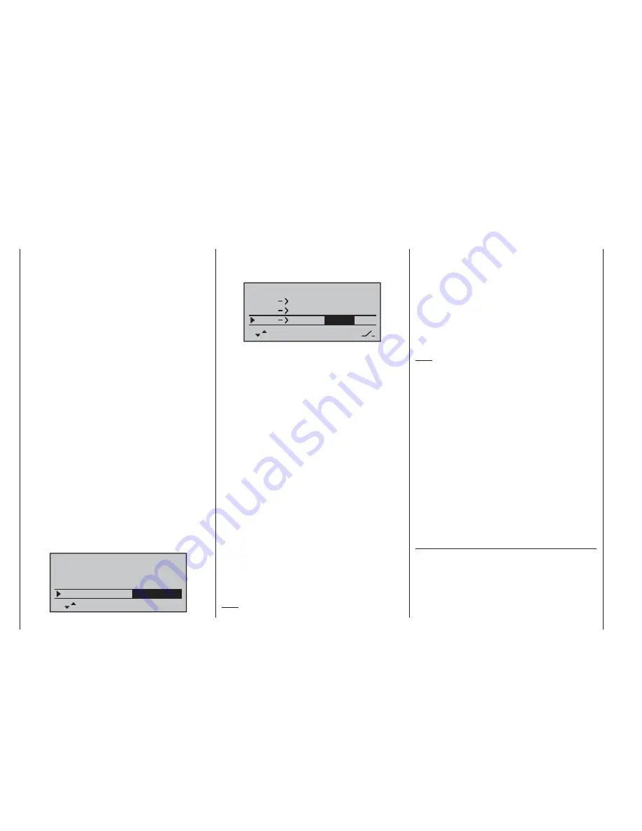
… and if you wish to be able to defl ect both ailerons up
using the throttle / brake stick (Ch 1), then a suitable
value should be entered in the “brak
¼
aile” line.
+
0%
SEL
+
0%
+
0%
+
0%
d i f f a i l e .
a i l
rudd
brak
brak
elev
aile
In principle the same applies to the “
brak
¼
fl ap
” line,
which also becomes available if you have selected
“2ail 2fl ”, although the set value should ensure that the
fl aps defl ect as far as possible in the downward direc-
tion when the brake stick is operated. It is important to
ensure that the servos do not strike their mechanical
end-stops.
If the ailerons are set up to act as simple brakes, or as
part of the braking arrangement in a butterfl y (crow) sys-
tem, then you should
always
enter a value for “
diff-red
”
(“differential reduction” – see page 76) – setting 100% is
the safe option here!
Differential reduction means that aileron differential
is suppressed proportionally when you operate the
airbrake stick. The purpose of this is to increase the
down-going aileron travel on the landing approach, with
the aim of improving aileron response.
If the wing is equipped with two camber-changing fl ap
servos in addition to two separately actuated ailerons,
then the “
ail
¼
fl ap
” (aileron à fl ap) mixer transfers the
aileron movements to the fl aps; we suggest that the
fl aps should not follow the movement of the ailerons to a
greater extent than about 50%.
Note:
If you have only installed one fl ap servo, then leave this
mixer at 0%.
The “
fl ap
¼
aile
” (fl ap à aileron) mixer works in the
opposite direction; depending on the layout of the model
we suggest values between about 50% and 100% for
this option. The fl aps are controlled using the transmitter
control or switch assigned to the input “E6”. Preferably,
however, the INC / DEC buttons (CTRL 5 and 6) should
be used for this, as their position is automatically stored
separately for each fl ight phase.
Note:
We strongly recommend that you reduce the travel of
the fl aps in the »
contr set.
« menu, as this gives fi ner
control of the fl ap positions using the selected transmit-
ter control.
The remaining options in the »
wing mixer
« menu are
designed to provide further fi ne-tuning of multi-fl ap wing
systems, and are largely self-explanatory.
When you have completed the model-specifi c settings
up to this point, you are probably ready to consider the
model’s fi rst fl ight. At this juncture you should certainly
take the time to carry out a series of “dry runs”, i. e.
check all the settings thoroughly while the model is still
on the ground. Remember that a serious programming
error may damage more than just the model. If you are
not sure of any point, please ask an experienced model
pilot for advice.
If during the test phase you realise that one or other of
the settings needs to be changed in order to tailor the
model’s control response to your preferences – perhaps
the servo travels are too great or too small overall – then
we suggest that you turn to the following menu …
Summary of Contents for mx-16 ifs
Page 1: ...mx 16 Programming Manual mx 16iFS 1 gb 3D CYLINDER ROTARY SELECT INTELLIGENT FREQUENCY SELECT...
Page 15: ...15 For your notes...
Page 31: ...31 For your notes...
Page 35: ...35 For your notes...
Page 39: ...39 For your notes...
Page 55: ...55 For your notes...
Page 65: ...65 For your notes...
Page 77: ...77 For your notes...
Page 104: ...104 For your notes...
Page 111: ...111 For your notes...
Page 128: ...128 For your notes 128...
Page 129: ...129 For your notes 129...
Page 130: ...130 For your notes...


