53
Program description: basic settings – model helicopter
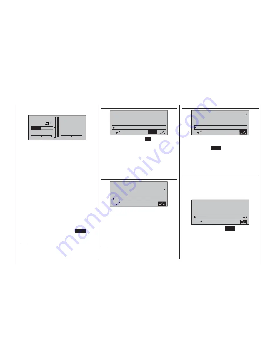
that the stopwatch switches to the “Timer” function; see
top right in the next illustration.
STARLET
#02
5:38h
stop
flt
«normal »
K78
IFS
10:01
0:00
9.6
V
When you operate the assigned switch, the stopwatch
starts from the set initial value, counting down (“Timer
function”). When the set time has elapsed, the timer
does not stop, but continues to run so that you can read
off the time elapsed after reaching zero. To make this
clear, the over-run time is shown highlighted (inverse
video).
Sequence of sounds
30 sec. before zero: triple beep
single beep every two seconds
20 sec. before zero: double beep
single beep every two seconds
10 sec. before zero: single beep
single beep every second
5 sec. before zero: single beep every second at higher
rate
zero: longer beep; display switches to
inverse video
The “alarm timer” is reset by pressing the
CLEAR
button
once you have halted the timer.
Note:
A count-down timer is indicated in the basic display by
a fl ashing colon (:) between the minutes fi eld and the
seconds fi eld.
Phase 2
rotor direct
left
pitch min
clock
front
10:01
SEL
SEL
C3
phase 2
hover
SEL
In the “phase 2” line you use the
SEL
fi eld to select a
suitable name from the six default names provided,
using the rotary cylinder. You can also assign a switch
using the switch symbol at bottom right.
More on the meaning of fl ight phases and how to
program them can be found in the section entitled “Flight
phase-specifi c mixers for collective pitch, throttle and tail
rotor” starting on page 78.
Auto-rotation
pitch min
clock
front
10:01
SEL
SEL
C3
phase 2
hover
SEL
autorotat.
The name “Auto-rotation” is permanently assigned to
Phase 3, and cannot be altered. The only available op-
tion is to assign a switch to it using the switch symbol at
bottom right of the screen.
For more information on programming fl ight phases
please refer to the »
heli mixer
« section starting on page
78.
Note:
The “Auto-rotation” fl ight phase ALWAYS has prec-
edence over all other fl ight phases.
Trainer / student
clock
10:01
SEL
SEL
C3
phase 2
hover
SEL
autorotat.
train. / stu.
In this menu line you can assign a “transfer switch” for
Trainer (teacher / pupil) mode operations, after pressing
the rotary cylinder or
ENTER
, as described on page 33.
The switch is used to transfer control from one transmit-
ter to the other.
For more information on Trainer systems please refer to
page 122.
Receiver output
For maximum fl exibility in terms of receiver socket as-
signment, the
mx
-16iFS software provides the means
to swap over the servo outputs 1 to max. 8; this is
carried out on the second page of the “Receiver output”
sub-menu.
vorn
SEL
phase 2
hover
autorotat.
train. / stu.
receiv out
Press the rotary cylinder or the
ENTER
button to move
to the next page of the display. Here you can assign
the “control channels” for servos 1 … 8 to any receiver
output you wish to use. However, please note that the
display in »
servo display
« – which you can reach by
pressing the rotary cylinder from the basic display – re-
fers exclusively to the “control channels”, i. e. the outputs
Summary of Contents for mx-16 ifs
Page 1: ...mx 16 Programming Manual mx 16iFS 1 gb 3D CYLINDER ROTARY SELECT INTELLIGENT FREQUENCY SELECT...
Page 15: ...15 For your notes...
Page 31: ...31 For your notes...
Page 35: ...35 For your notes...
Page 39: ...39 For your notes...
Page 55: ...55 For your notes...
Page 65: ...65 For your notes...
Page 77: ...77 For your notes...
Page 104: ...104 For your notes...
Page 111: ...111 For your notes...
Page 128: ...128 For your notes 128...
Page 129: ...129 For your notes 129...
Page 130: ...130 For your notes...


