background image

134


User 

Manual 


GWG Gateway


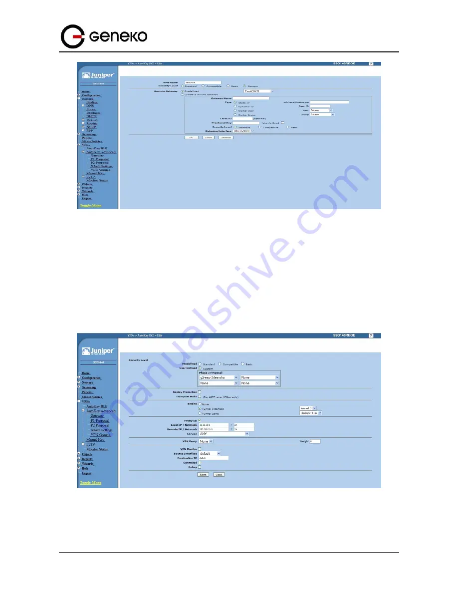
Figure 

121

 – AutoKey IKE parameters


Click 

Advanced

 button.


-


Security level – User defined: 

custom,


-


Phase 2 proposal:

 pre–g2–3des–sha,


-


Bind to – Tunnel interface:

 tunnel.3(from


step 1),


-


Proxy ID:

 Enabled,


-


LocalIP/netmask:

 10.10.10.0/24,


-


RemoteIP/netmask:

 192.168.10.0/24, 

-


Click 

Return

 and 

OK


Figure 

122

 – AutoKey IKE advanced parameters


Step 4 – Routing


Summary of Contents for GWG

Page 1: ...GWG Gateway USER MANUAL GWG Document version 1 0 1 Date July 2016 WWW GENEKO RS ...

Page 2: ...ja Savić Firmware version 1 0 10 28 07 2016 User Manual Tanja Savić Firmware version 1 1 0 Document Approval The following report has been accepted and approved by the following Signature Printed Name Title Date Dragan Marković Executive Director 24 12 2015 Dragan Marković Executive Director 28 07 2016 ...

Page 3: ...ATION 28 ADD REMOVE UPDATE MANIPULATION IN TABLES 29 SAVE RELOAD CHANGES 29 STATUS INFORMATION 30 Status General 30 Status LAN Port Information 30 Status DHCP 31 Status Mobile Information 31 Status Firewall 32 Status Router Monitoring 33 Status GPS 33 SETTINGS LAN PORTS 34 SETTINGS DHCP SERVER 35 SETTINGS MOBILE SETTINGS 36 SETTINGS ROUTING 38 Port forwarding 40 Settings Demilitarized Zone DMZ 42 ...

Page 4: ...n File 85 Export Configuration File 85 Maintenance Default Settings 85 Maintenance System Reboot 86 MANAGEMENT TIMED ACTIONS 86 MANAGEMENT COMMAND LINE INTERFACE 87 MANAGEMENT REMOTE MANAGEMENT 88 MANAGEMENT CONNECTION MANAGER 89 MANAGEMENT SIMPLE MANAGEMENT PROTOCOL SNMP 93 MANAGEMENT LOGS 94 LOGOUT 95 CHROOT 95 CONFIGURATION EXAMPLES 97 GWG GATEWAY AS INTERNET GATEWAY 97 GRE TUNNEL CONFIGURATION...

Page 5: ...igure 19 Routing configuration page 39 Figure 20 Port forwarding 40 Figure 21 DMZ configuration page 42 Figure 22 RIP configuration page 43 Figure 23 VRRP 46 Figure 24 GRE tunnel parameters configuration page 47 Figure 25 IPSec Summary screen 49 Figure 26 IPSec Settings 51 Figure 27 OpenVPN example 55 Figure 28 Open VPN Summary screen 55 Figure 29 OpenVPN configuration page 58 Figure 30 PPTP confi...

Page 6: ...igure 74 GRE configuration page for GWR Router 1 99 Figure 75 Routing configuration page for GWG Gateway 1 100 Figure 76 Network configuration page for GWR Router 2 100 Figure 77 GRE configuration page for GWG Gateway 2 101 Figure 78 Routing configuration page for GWG Gateway 2 101 Figure 79 GRE tunnel between Cisco router and GWG Gateway 103 Figure 80 LAN Port configuration page 104 Figure 81 GRE...

Page 7: ...y advanced parameters 133 Figure 120 AutoKey IKE 133 Figure 121 AutoKey IKE parameters 134 Figure 122 AutoKey IKE advanced parameters 134 Figure 123 Routing parameters 135 Figure 124 Policies from untrust to trust zone 135 Figure 125 Policies from trust to untrust zone 136 Figure 126 Multipoint OpenVPN topology 137 Figure 127 OpenVPN application settings 138 Figure 128 OpenVPN GWG settings 140 Fig...

Page 8: ...ters 64 Table 20 CRL Certificates 65 Table 21 Preshared Key Files 66 Table 22 Firewall parameters 68 Table 23 MAC filtering parameters 68 Table 24 DynDNS parameters 70 Table 25 Serial Port over TCP UDP parameters 72 Table 26 Modbus gateway parameters 74 Table 27 GPIO Parameters 80 Table 28 Device Identity Parameters 81 Table 29 Authentication parameters 82 Table 30 Date time parameters 83 Table 31...

Page 9: ... VPN Security powerful options When coupled with the rich embedded intelligence it is the perfect choice for a broad set of M2M solutions GWG comes with numerous connectivity options and multiple configuration methods It allows you to connect your existing Ethernet and serial devices using basic configuration Besides Ethernet RS 232 and RS 485 serial ports the device is equipped with USB port as w...

Page 10: ... Vehicle based bank service POS Vending machine Bank office supervision Security Traffic control Video Surveillance Solutions Other Remote Office Solution Remote Access Solution There are numerous variations of each and every one of above listed applications Therefore GENEKO formed highly dedicated top rated support team that can help you analyze your requirements and existing system chose the rig...

Page 11: ...SMA Center pin female SIM Slots 1 Wireless Interfaces 3G WWAN Cinterion PHS8 E UMTS HSPA 900 2100 MHz Transfer rate max 14 4 Mbps down 5 76 Mbps up GSM GPRS EDGE 900 1800 MHz Transfer rate max 384 Kbps down 384 Kbps up GSM Connectors 1 or 2 x 50 Ω SMA Center pin female SIM Slots 1 Wireless Interfaces GNSS Cinterion PLS8 E PHS8 E GNSS Systems GPS GLONASS GNSS Tracking Sensitivity 159 dBm GNSS Acqui...

Page 12: ...D CTS RTS Flow Control Software XON XOFF Hardware CTS RTS Connector D SUB 9 female Pinout 2 TX 3 RX 5 GND 7 CTS 8 RTS remaining pins NC Wired Interfaces RS 485 RS 422 Ports 1 Standard RS 485 RS 422 4 wires Full Duplex Data Rate 10 Mbps On Board Termination None Connector Phoenix 1844249 Pinout 1 RX 2 RX 3 TX 4 TX 5 GND Wired Interfaces USB Ports 1 ...

Page 13: ...uts 3 user selectable input or output Digital Inputs with internal weak pull up active when pulled down to GND Digital Outputs open drain 4 28V no over current protection Connector Phoenix 1844249 Pinout 1 5VDC with 500mA resettable PTC fuse 2 IO1 3 IO2 4 IO3 5 GND Wired Interfaces Digital Input Output available on Power Connector Digital Inputs Outputs 1 output 1 ignition sense input Digital Outp...

Page 14: ...Protection Reverse polarity transients overcurrent internal 2 A resettable PTC fuse Consumption at 12 VDC Hibernation GPS OFF GSM OFF TBD mA Sleep GPS OFF GSM wake up on SMS or call TBD mA Typical GPS ON GSM ON 150 mA Peak GPS ON GSM TX burst for 577 s every 4 615 ms 1 A Connector Molex 43045 0400 Pinout 1 9 36VDC also Analog Input 2 GND 3 Ignition Sense Input 4 Digital Output Physical Dimensions ...

Page 15: ...arately Environmental Operating Temperature 20 C to 70 C Storage Temperature 40 C to 85 C Relative Humidity 5 to 95 non condensing IP rating IP40 Ethernet Isolation 1 5 kV RMS RS 485 Port Protection ESD 2 kV Approvals Safety EN 60950 1 2006 A1 2010 A2 2013 A11 2009 A12 2011 EMC EN 301 489 1 V1 9 2 EN 301 489 7 V1 3 1 EN 301 489 17 V2 1 1 EN 301 489 24 V1 5 1 Radio Spectrum EN 301 511 v9 0 2 EN 301...

Page 16: ...m x 14 mm Accessories optional AC DC adapter Input 90 264 VAC 47 63 Hz Output 12 V 1A GSM antenna extension cable with magnetic base Cable length 3 m Cable connector SMA Center pin male Magnet base connector SMA Center pin female Magnet base dimensions D x H 50 mm x 40 mm Active uBlox GPS antenna with magnetic base Cable length 5 m Cable connector SMA Center pin male Frequency 1575 3 MHz LNA Gain ...

Page 17: ...dynamic DNS service offered at http www ez ip net http www justlinux com http www dhs org http www dyndns org http www ods org http www dyn ca http www tzo com http www easydns com http www dyns cx http www zoneedit com http www no ip org NTP NTP Network Time Protocol is a protocol for synchronizing the clocks of router Serial port Modbus gateway carries out translation between Modbus TCP and Modb...

Page 18: ...ilover Defines number of failed IKE negotiation attempts before failover IPSec tunnel failover Switches to another provider when tunnel performance is bad or one provider is unavailable IPSec max number of tunnels 3 OpenVPN OpenVPN is a full featured SSL VPN solution for securing communications via the Internet Implements OSI layer 2 or 3 secure network extension using the industry standard SSL TL...

Page 19: ...ed for peer authentication In cryptography a client certificate is a type of digital certificate that is used by client systems to make authenticated requests to a remote server Client certificates play a key role in many mutual authentication designs providing strong assurances of a requester s identity There are options to first browse for the file then to upload the file After one or more files...

Page 20: ...ns that Modbus serial slaves can be directly attached to the unit s serial ports without any external protocol converter USB port USB host port is available and highly customized for our users With additional implementation in software user now can use more than one usb storage on the device exactly up to eight partitions on one medium or usb mediums extended with usb hub By default first partitio...

Page 21: ...t Protocol is a network protocol that provides network administrators with the ability to monitor the status of the GWG 30 40 gateway and receive notification of any critical events as they occur on the network The GWG 30 40 gateway supports SNMP v1 v2c and all relevant Management Information Base II MIBII groups Traffic and event log Log tracing Connection Manager Enabling Connection Manager will...

Page 22: ... RS 485 connector One USB connector for connection to the PC Ethernet connector LED ACT yellow on Network traffic detected off when no traffic detected Network Link green LED on Ethernet activity or access point engaged Figure 2 GWG Gateway front panel Back panel On the back panel of device the following connectors are located Power supply connectors SMA connector for connection of the GSM UMTS LT...

Page 23: ...en Reset to Factory Defaults To restore the default settings of the GWG Gateway hold the RESET button pressed for a few seconds Restoration of the default configuration will be signaled by blinks of the power LED on the top panel and the side This will restore the factory defaults and clear all custom settings of the GWG Gateway You can also reset the GWG Gateway to factory defaults using the Main...

Page 24: ...work coverage at the location Flashing Green A bad or marginal signal is present RSSI 85dBm or 110 dBm Green A good signal is present RSSI 85dBm Network LED This monitors the cellular network Off The device was unable to authenticate on the network Flashing green slow The cellular network is found and the device is connecting Green Connected to the cellular network Flashing Green fast The device i...

Page 25: ...ring the GWG Gateway Configuration administration and monitoring of the GWG Gateway can be performed through the web interface The default IP address of the router is 192 168 1 1 Another method is by Command Line Interface CLI This method has limited options for configuring the GWG Gateway but still represents a very powerful tool when it comes to gateway setup and monitoring Another document deal...

Page 26: ...na to gateway Make sure to tighten antenna so it is not loose Plug AC DC adapter 9 36VDC cable into POWER CONNECTOR on the gateway Red wire power Black wire ground Green wire GPIO output White wire ignition All wires must be isolated Figure 7 Wires for power ground GPIO output ignition ...

Page 27: ...left side of the screen If SIM card is present ENABLED check box will be checked Otherwise you need to insert SIM card as explained in Inserting SIM cards chapter Your GSM operator should provide you with PROVIDER USERNAME optional PASSWORD optional APN and PIN optional information Make sure you enter this into corresponding fields and then click on SAVE button Flashing red NETWORK indicator will ...

Page 28: ... 1 in the address field A login screen prompts you for your Username and Password Default administration credentials are admin admin If you want to use web interface for gateway administration please enter IP address of gateway into web browser Please disable Proxy server in web browser before proceed Figure 8 User authentication After successfully finished process of authentication of Username Pa...

Page 29: ...Add link To Update the row in the table Change data directly in fields you want to change To Remove the row from the table Click Remove link to remove selected row from the table Save Reload changes To save all the changes in the form press Save button By clicking Save data are checked for validity If they are not valid error message will be displayed To discard changes press the Reload button By ...

Page 30: ... Current Time UpTime Total Memory Used Memory Free Memory MAC Address Screenshot of General Gateway information is shown at Error Reference source not found Data in Status menu are read only and cannot be changed by user If you want to refresh screen data press Refresh button SIM Card detection is performed only at time booting the system and you can see the status of SIM slot by checking the Enab...

Page 31: ...11 DHCP Information Status Mobile Information Mobile Information Tab provides information about GPRS EDGE HSPA HSPA LTE connection and traffic statistics Mobile information menu has three submenus which provide information about GPRS EDGE HSPA HSPA LTE mobile module manufacturer and model Mobile operator and signal quality Mobile traffic statistics in bytes Screenshot of Mobile information from th...

Page 32: ...eway If Local DNS is configured it has priority to those DNS servers Status Firewall Firewall Information Tab provides information about active firewall rules divided in three groups INPUT FORWARD and OUTPUT chain Each of these groups has packet counter which can be cleared with one of three displayed button Reset INPUT Reset FORWARD and Reset OUTPUT Figure 13 Firewall Information ...

Page 33: ...d information about Mobile Connection You can activate Automatic refresh after 5 10 15 30 or 60 seconds Figure 14 Router monitoring 1 Figure 15 Router monitoring 2 Status GPS This page will show a graphical view of router s location Modem must provide capabilities of GPS the router must be connected to GPS antenna coordinates are connected and GPS support is enabled GPS ...

Page 34: ...lt IP address Subnet Mask The subnet mask specifies the network number portion of an IP address The GWG Gateway support sub netting You must specified subnet mask for your LAN TCP IP settings Gateway Type the IP address of your local gateway Use Local Gateway option carefully Gateway becomes unreachable from local subnet when this option is entered Alias IP Address IP address of internal virtual L...

Page 35: ...is field specifies last of the contiguous addresses in the IP address pool Lease Duration This field specifies DHCP session duration time Gateway This field specifies default gateway for DHCP clients If left blank router will become the gateway Network netmask This field shows current network and netmask of the gateway DHCP server Primary DNS Secondary DNS This field specifies IP addresses of DNS ...

Page 36: ...oad to discard any changes and reload previous settings Table 4 DHCP Server parameters Figure 17 DHCP Server configuration page Settings Mobile Settings Click Mobile Settings Tab to open the Mobile Settings screen Use this screen to configure the GWG Gateway GPRS EDGE HSPA HSPA LTE parameters on Figure 18 ...

Page 37: ...k Mobile provider will assign you specific username for SIM card Password This field specifies Password for client authentication at GSM UMTS network Mobile provider will assign you specific password for each SIM card APN This field specifies APN for client authentication at GSM UMTS network Mobile provider will assign you specific APN for SIM card Connection Type This field enables you to choose ...

Page 38: ...ck to the GWG Gateway Refresh Click Refresh to see updated mobile network status Connect Disconnect Click Connect Disconnect to connect or disconnect from mobile network Table 5 Mobile settings Figure 18 shows screenshot of GSM UMTS LTE tab configuration menu GSM UMTS LTE menu is divided into two parts Upper part provides all parameters for configuration GSM UMTS LTE connection These parameters ca...

Page 39: ...fies the IP netmask address of the final destination Gateway This parameter specifies the IP network address of the final destination Routing is always based on network number If you need to specify a route to a single host use a subnet mask of 255 255 255 255 in the subnet mask field to force the network number to be identical to the host ID Metric Metric represents the cost of transmission for r...

Page 40: ...ocol This field specifies the IP protocol type Choose between TCP and UDP protocol Source IP This field specifies incoming IP address for which port forwarding is configured Source Netmask This field specifies incoming IP address netmask for allowed IP subnet Source Interface Select interface where port forwarding is done Port forwarding from outside WAN interface to inside LAN interface is done o...

Page 41: ... to delete selected item from table Reload Click Reload to discard any changes and reload previous settings Save Click Save to save your changes back to the GWG Gateway After pressing Save button it make take more than 10 seconds for router to save parameters and become operational again Table 7 Port forwarding ...

Page 42: ...DMZ settings is enabled at the GWG Gateway IP address from LAN IP address which will be exposed to the Internet This will secure rest of the internal network from external access Reload Click Reload to discard any changes and reload previous settings Save Click Save to save your changes back to the Geneko Gateway Table 8 DMZ parameters Routing Information Protocol RIP The Routing Information Proto...

Page 43: ...43 User Manual GWG Gateway Figure 22 RIP configuration page ...

Page 44: ...nsole in order to be returned after router reboot or export of configuration It is done with command ripd write or ripd copy running config startup config RIP routing engine for the GWG Gateway Use telnet to enter in global configuration mode telnet 192 168 1 1 2602 telnet to br0 at TCP port 2602 After telnet type enable followed by conf t and router rip to enter RIP configuration mode To associat...

Page 45: ...first type exit if you are at ripd config router to get up from config router to config mode ripd config interface greX ripd config if ip rip send version VERSION ripd config if ip rip receive version VERSION Disable rip authentication at an interface ripd config if no ip rip authentication mode md5 text Debug commands ripd config debug rip ripd config debug rip events ripd config debug rip packet...

Page 46: ...s authentication or content encryption VPNs for example can be used to separate the traffic of different user communities over an underlying network with strong security features A VPN may have best effort performance or may have a defined Service Level Agreement SLA between the VPN customer and the VPN service provider Generally a VPN has a topology more complex than point to point The distinguis...

Page 47: ...This check box allows you to activate deactivate VPN GRE traffic Local Tunnel Address This field specifies local IP address of virtual tunnel interface Local Tunnel Netmask This field specifies the IP netmask address of virtual tunnel This field is unchangeable always 255 255 255 252 Tunnel Source This field specifies IP address or hostname of tunnel source Tunnel Destination This field specifies ...

Page 48: ...eckbox to enable this feature Keepalives do not have to be configured on both ends of the tunnel in order to work a tunnel is not aware of incoming keepalive packets You should define the time interval in seconds between transmitted keepalive packets Enter a number from 1 to 60 seconds and the number of times to retry after failed keepalives before determining that the tunnel endpoint is down Ente...

Page 49: ...tunnels This is the number of available not yet defined IPSec tunnels No This filed indicates the number of the IPSec tunnel Name This field shows the Tunnel Name that you gave to the IPSec tunnel Enabled This field shows if tunnel is enabled or disabled After clicking on Start button only enabled tunnels will be started Status Field indicates status of the IPSec tunnel Click on Refresh button to ...

Page 50: ...arts the IPSec negotiations between all defined and enabled tunnels If the IPSec is already started Start button is replaced with Restart button Stop This button will stop all IPSec started negotiations Refresh Click on this button to refresh the Status field in the Summary table Table 12 IPSec Summary To create a tunnel click Add New Tunnel button Depending on your selection the Local Group Setup...

Page 51: ...ity Gateway Type selected on the IPSec device at the other end of the tunnel IP Address The WAN or Internet IP address of the GWG Gateway automatically appears If the GWG Gateway is not yet connected to the GSM UMTS LTE network this field will be blank Local ID type Authentication identity for one of the participant It can be an IP address or a fully qualified domain name preceded by When using ce...

Page 52: ...ryption decryption and authentication This is done by sharing a key for the encryption code For key management the Geneko Router uses only IKE with Preshared Key mode Key Exchange mode IKE with Preshared Key IKE is an Internet Key Exchange protocol used to negotiate key material for Security Association SA IKE uses the Preshared Key to authenticate the remote IKE peer Both ends of IPSec tunnel mus...

Page 53: ...ot need to set the Phase 2 DH Group There are three groups of different prime key lengths Group 1 is 768 bits Group 2 is 1024 bits and Group 5 is 1536 bits long If network speed is preferred select Group 1 If network security is preferred select Group 5 You do not have to use the same DH Group that you used for Phase 1 but both ends of the IPSec tunnel must use the same Phase 2 DH Group Phase 2 En...

Page 54: ...ction Dead Peer Detection DPD When DPD is enabled the Geneko Router will send periodic HELLO ACK messages to check the status of the IPSec tunnel this feature can be used only when both peers or IPSec devices of the IPSec tunnel use the DPD mechanism Once a dead peer has been detected the Geneko Router will disconnect the tunnel so the connection can be re established Specify the interval between ...

Page 55: ... SSLv3 TLSv1 protocol and contains many security and control features The server and client have almost the same configuration The difference in the client configuration is the remote endpoint IP or hostname field Also the client can set up the keepalive settings For successful tunnel creation a static key must be generated on one side and the same key must be uploaded on the opposite side Figure ...

Page 56: ...l Edit This link opens screen where you can change the tunnel s settings Add New Tunnel Click on this button to add a new OpenVPN tunnel After you have added the tunnel you will see it listed in the Summary table Start This button starts the OpenVPN negotiations between all defined and enabled tunnels If the OpenVPN is already started Start button is replaced with Restart button Stop This button w...

Page 57: ...6 or 20 bytes per packet Set none to disable authentication Protocol Select a protocol you want to use for tunnel connection UDP connect and TCP client will need the Remote Host or IP Adress field in order to successfully establish a tunnel UDP Port TCP Port Enter a port number for a tunnel connection LZO Compression Use fast LZO compression This may add up to 1 byte per packet for incompressible ...

Page 58: ...the IP address of the local VPN endpoint of local tunnel interface Remote Interface IP Address This is the IP address of the remote VPN endpoint of remote tunnel interface Network Topology Configure virtual addressing topology net30 use a point to point topology by allocating one 30 subnet per client p2p use a point to point topology where the remote endpoint of the client s tunnel interface alway...

Page 59: ...mote Netmask Netmask of remote subnet to route Domain Some PPTP servers require domain name of authentication Username Username to authenticate to the remote server Password Password to authenticate to the remote server Encryption Leave this option enabled to use default MPPE Microsoft encryption and MPPC Microsoft compression protocols Persist If this option enabled to use default MPPE Microsoft ...

Page 60: ...ed before a session can be placed in the tunnel Figure 32 L2TP configuration page L2TP Label Description Number Selected tunnel number Number of L2TP tunnels is limited to 5 Enabled Select this option to enable L2TP tunnel Tunnel name Unique tunnel identifier Local IP address Set the IP address of the local interface to be used for the tunnel This address must be the address of a local interface T...

Page 61: ...ssigned to the session by the peer The value used must match the session ID value being used at the peer Peer Cookie Sets an optional peer cookie value to be assigned to the session This is a 4 or 8 byte value specified as 8 or 16 hex digits e g 014d3636deadbeef The value must match the cookie value set at the peer It tells the local system what cookie value to expect to find in received L2TP pack...

Page 62: ...owse for the file then to upload the file After one or more files are uploaded a table with uploaded files is shown with the option to delete each of them if they are no longer needed CA Certificate Label Description No Ordinal number of the file File Filename of the file Action Action field shows the delete button for deleting the file Select file This field shows the browse button for finding th...

Page 63: ...order to apply for a digital identity certificate Before creating a CSR the applicant first generates a key pair keeping the private key secret The CSR contains information identifying the applicant such as a distinguished name in the case of an X 509 certificate which must be signed using the applicant s private key The CSR also contains the public key chosen by the applicant The CSR may be accom...

Page 64: ...g the file Details Details button for displaying details about the certificate issuer valid from valid until Select file for upload This field shows the browse button for finding the file on local computer which will be uploaded Upload This is the upload button it is used to start the upload of the file Table 19 Private Key parameters ...

Page 65: ... t c CRL Certificate Label Description Filename Filename of the file Delete Delete button for deleting the file Details Details button for displaying details about the certificate issuer valid from valid until Select file for upload This field shows the browse button for finding the file on local computer which will be uploaded Upload This is the upload button it is used to start the upload of the...

Page 66: ...ill be uploaded Upload This is the upload button it is used to start the upload of the file Table 21 Preshared Key Files Figure 38 Preshared Key screen Settings Firewall IP Filtering TCP IP traffic flow is controlled over IP address and port number through router s interfaces in both directions With firewall options it is possible to create rule which exactly matches traffic of interest Traffic ca...

Page 67: ...specifies a custom defined values Protocol The protocol of the rule or of the packet to check The specified protocol can be one of All TCP UDP UDPLITE ICMP ESP AH SCTP or it can be a numeric value from 0 to 255 representing one of these protocols or a different one The number zero is equivalent to all Protocol all will match with all protocols and is taken as default when this option is omitted Po...

Page 68: ...of Service is disabled or enabled Edit This link opens screen where you can change the rule s settings Delete Click on this link to delete the rule and all settings for that particular rule Add New Rule Click Add New Rule to add a new firewall rule After you have added the rule you will see it listed in the Summary table Apply rules Click Add New Rule to add a new firewall rule After you have adde...

Page 69: ...ng this feature firstly you should register to DDNS service provider Section of the web interface where you can setup DynDNS parameters is shown in Figure 41 Figure 41 DynDNS settings DynDNS Label Description Enable DynDNS Cilent Enable DynDNS Client Service The type of service that you are using try one of no ip dhs pgpow dyndns dyndns static dyndns custom ods easydns dyns justlinux and zoneedit ...

Page 70: ... Time between update retry attempts default value is 1800 Reload Click Reload to discard any changes and reload previous settings Save Click Save to save your changes back to the GWR Router Table 24 DynDNS parameters Settings Serial Port 1 The Geneko GWG Gateway provides a way for a user to connect from a network connection to a serial port It provides all the serial port setup a configuration fil...

Page 71: ... This provides a way for a user to connect from a network connection to a serial port Modbus gateway settings Enable translation between Modbus TCP and Modbus RTU Bits per second The unit and attached serial device such as a modem must agree on a speed or baud rate to use for the serial connection Valid baud rates are 300 1200 2400 4800 9600 19200 38400 57600 or 115200 Data bits Indicates the numb...

Page 72: ...es the TCP port number on which the server will listen for connections The value entered should be a valid TCP port number The default Modbus TCP port number is 502 Connection timeout When this field is set to a value greater than 0 the server will close connections that have had no network receive activity for longer than the specified period Transmission mode Select RTU based on the Modbus slave...

Page 73: ... be directly attached to the unit s serial ports without any external protocol converters Click Serial Port Tab to open the Modbus Gateway configuration screen Choose Modbus Gateway settings to configure Modbus At the Figure 44 Modbus gateway configuration page you can see screenshot of Modbus Gateway configuration menu Modbus Gateway Settings Label Description TCP accept port This field determine...

Page 74: ...ause between requests in milliseconds Valid values are between 1 and 10000 Default value is 100 Maximum number of retries If no valid response is received from a Modbus slave the value in this field determines the number of times the serial server will retransmit request before giving up Log level Set importance level of log messages Reload Click Reload to discard any changes and reload previous s...

Page 75: ...With additional implementation in software user now can use more than one usb storage on the device exactly up to eight partitions on one medium or usb mediums extended with usb hub By default first partition is reserved for logging feature and will automatically mounted as log partition Web interface configuration for external message logging is presented at Figure 46 ...

Page 76: ...tically mounted under chroot work environment and become available under media usbx right after usb is being inserted Note x represents current available partitions mounted in ascending order Example of usage custom partitions is represented at Figure 47 Figure 47 USB multi partition mounted ...

Page 77: ...status user should send SMS containing following string PPP STATUS After the command is executed router sends one of the following status reports to the user CONNECTING CONNECTED WAN_IP WAN IP address or the router DISCONNECTING DISCONNECTED 5 In order to establish PPP connection over the other SIM card user should send SMS containing following string SWITCH SIM After the command is executed route...

Page 78: ...S Send SMS SMS send feature allows users to send SMS message from WEB interface In following picture is page where SMS can be sent There are two required fields on this page Phone number and Message Sending SMS messages is possible with this application The SMS message will be sent after entering Phone number and Message and by pushing button Send Figure 49 Send SMS ...

Page 79: ...r restore factory default settings Maintenance System Control Create a scheduled task to reboot the device at a regular interval Figure 50 System Control Maintenance LED Select the side of the router on which will the LEDs be active LEDs are located on the top and on the side of the router housing Figure 51 LED Maintenance GPIO GPIO General purpose input output sends SMS when some certain event oc...

Page 80: ...PIO pin change its state to Low or High Selecting an action will open a new SMS settings section for setting the parameters Destination phone Recipient phone numbers SMS header Text of the message which will be sent SMS text Click Reload to discard any changes and reload previous settings Save Click Save button to save your changes back to the GWG Gateway Reload Click Reload to discard any changes...

Page 81: ... of the GWG Gateway Only for information purpose Location This field specifies location of the GWG Gateway Only for information purpose Save Click Save button to save your changes back to the GWR Router Reload Click Reload to discard any changes and reload previous settings Table 28 Device Identity Parameters Figure 53 Device Identity Settings configuration page Maintenance Authentication By Admin...

Page 82: ...e Enable or disable usage of this radius server Server Enter remote radius server IP address or hostname Port Enter remote radius server port Shared secret Enter remote radius server shared secret Timeout Enter remote radius server timeout in seconds 1 60 Save Click Save button to save your changes back to the GWG Gateway Whether you make changes or not gateway will reboot every time you click Sav...

Page 83: ...lly Time Date This field species Date and Time information You can change date and time by changing parameters Time Protocol Specify time protocol Currently only NTP is supported Time Server Address Enter the Hostname or IP address of the NTP server Automatically synchronize NTP Setup automatic synchronization with time server Update time every Time interval for automatic synchronization Time Zone...

Page 84: ...eed to download the latest version of the GWG Gateway firmware please visit Geneko support site Follow the on screen instructions to access the download page for the GWG Gateway If you have already downloaded the firmware onto your computer click Browse button on Update firmware Tab to look for the firmware file After selection of new firmware version through Browse button mechanism the process of...

Page 85: ...uration file After you select the file click Import This process may take up to a minute Restart the Router in order to changes will take effect Export Configuration File To export the Router s current configuration file select the part of the configuration you would like to backup and click Export By default this file will be called Configuration tar gz This file contains confFile bkg cacert and ...

Page 86: ...mends that you use the Reboot tool on this screen Click Reboot to have the GWG Gateway reboot This does not affect the router s configuration Figure 60 System Reboot page Management Timed Actions Create a schedule of actions to be performed in a certain time of the day There is a possibility to add more actions for each day of the week ...

Page 87: ...nterface settings screen Use this screen to configure CLI parameters Figure 61 Command Line Interface Command Line Interface Label Description CLI Settings Enable telnet service Enable or disable CLI via telnet service Enable ssh service Enable or disable CLI via ssh service View Mode Username Username for View mode View Mode Password Password for View mode Confirm Password Confirm password for Vi...

Page 88: ...e 62 Remote Management Remote Management Label Description Enable Remote Management Enable or disable Remote Management Protocol Choose between Geneko and Sarian protocol Bind to Specify the interface TCP port Specify the TCP port Save Click Save button to save your changes back to the Geneko Router Whether you make changes or not gateway will reboot every time you click Save Reload Click Reload t...

Page 89: ...tions of the gateway Connection Manager is enabled by default on the gateway and if you do not want to use it you can simply disable it Figure 63 Connection Manager Getting started with the Connection Wizard Connection Wizard is installed through few very simple steps and it is available immediately upon the installation It is only for Windows OS After starting the wizard you can choose between tw...

Page 90: ...rd inspects the network whole broadcast domain you ll see a list of routers and gateways present in the network with following information Serial number Model Ethernet IP Firmware version Pingable if Ethernet IP address of the router is in the same IP subnet as PC interface then this field will be marked i e you can access router over web interface ...

Page 91: ...nual GWG Gateway Figure 65 Connection Wizard Router Detection 1 Figure 66 Connection Wizard Router Detection 2 When you select one of the routers from the list and click Next you will get to the following screen ...

Page 92: ...click Next and you will be able to setup WAN interface Figure 68 Connection Wizard WAN Settings After entering the configuration parameters if you mark option Establish connection router will start with connection establishment immediately when you press Finish button If not you have to start connection establishment manually on the router s web interface ...

Page 93: ... disable SNMP Get Community Create the name for a group or community of administrators who can view SNMP data The default is public It supports up to 64 alphanumeric characters Set Community Create the name for a group or community of administrators who can view SNMP data and send SET commands via SNPM The default is private It supports up to 64 alphanumeric characters Service Port Sets the port o...

Page 94: ... into a central repository Figure 70 Syslog configuration page The GWR Router supports this protocol and can send its activity logs to an external server Syslog Settings Label Description Disable Mark this option in order to disable Syslog feature Local syslog Mark this option in order to enable Local syslog feature Logs will remain on the router Remote local syslog Mark this option in order to en...

Page 95: ...ogout The Logout tab is located on the down left hand corner of the screen Click this tab to exit the web based utility If you exit the web based utility you will need to re enter your Username and Password to log in and then manage the Gateway CHROOT A chroot environment is an operating system call that will change the root location temporarily to a new folder Chroot runs a command or an interact...

Page 96: ..._at_command uniq cat fgrep lsof seq unset cd fi lua service until chattr find luac set unzip chmod flock mapfile sh upfirmware clear for md5sum shift uptime cmp free microcom shopt users command ftpd mkdir show usleep compgen function mkfifo sleep vi complete fuser mobile activity sms_send wait compopt getopts modem_info snmp view wc configuration_export grep modem_state sort wget configuration_im...

Page 97: ...k 255 255 255 0 Click LAN Ports Tab to open the LAN Port Settings screen Use this screen to configure LAN TCP IP settings Configure IP address and Netmask IP address 10 1 1 1 Netmask 255 255 255 0 Press Save to accept the changes Use SIM card with a dynamic static IP address obtained from Mobile Operator Note the default gateway may show or change to an address such as 10 0 0 1 this is normal as i...

Page 98: ...o GWG Gateways The GWG Gateways requirements Static IP WAN address for tunnel source and tunnel destination address Source tunnel address should have static WAN IP address Destination tunnel address should have static WAN IP address GSM UMTS APN Type For GSM UMTS LTE networks GWG Gateway connections may require a Custom APN A Custom APN allows for various IP addressing options particularly static ...

Page 99: ... please click Connect button Click VPN Settings GRE to configure GRE tunnel parameters Enable yes Local Tunnel Address 10 10 10 1 Local Tunnel Netmask 255 255 255 252 Unchangeable always 255 255 255 252 Tunnel Source 1 10 251 49 2 obtained by the network provider 2 Select HOST from drop down menu if you want to use host name as peer identifier Tunnel Destination 1 10 251 49 3 obtained by the netwo...

Page 100: ...n the LAN Ports Settings screen Use this screen to configure LAN TCP IP settings Configure IP address and Netmask IP Address 192 168 2 1 Subnet Mask 255 255 255 0 Press Save to accept the changes Figure 76 Network configuration page for GWR Router 2 Use SIM card with a static IP address obtained from Mobile Operator Note the default gateway may show or change to an address such as 10 0 0 1 this is...

Page 101: ... the network provider 2 Select HOST from drop down menu if you want to use host name as peer identifier Tunnel Destination 1 10 251 49 2 obtained by the network provider 2 Select HOST from drop down menu if you want to use host name as peer identifier KeepAlive enable no Period none Retries none Press ADD to put GRE tunnel rule into GRE table Press Save to accept the changes Figure 77 GRE configur...

Page 102: ...102 User Manual GWG Gateway Optionally configure IP Filtering to block any unwanted incoming traffic On the device connected on GWG Gateway 2 setup default gateway 192 168 2 1 ...

Page 103: ...ter it appears that it has two paths to the remote physical interface and the tunnel interface running through the tunnel This tunnel could then transmit unroutable traffic such as NetBIOS or AppleTalk The GWG Gateway uses Network Address Translation NAT where only the mobile IP address is visible to the outside All outgoing traffic uses the GWG Gateway WAN VPN mobile IP address HQ Cisco router ac...

Page 104: ...nnel source FastEthernet0 0 tunnel destination 172 29 8 5 ip route 10 1 1 0 255 255 255 0 tunnel0 Command for tunnel status show ip interface brief The GWG Gateway Sample Configuration Click LAN Ports Tab to open the LAN Port Settings screen Use this screen to configure LAN TCP IP settings Configure IP address and Netmask IP Address 10 1 1 1 Subnet Mask 255 255 255 0 Press Save to accept the chang...

Page 105: ...s ADD to put GRE tunnel rule into VPN table Press Save to accept the changes Figure 81 GRE configuration page Configure GRE Route Click Static Routes on Routing Tab Parameters for this example are Destination Network 10 2 2 0 Netmask 255 255 255 0 Figure 82 Routing configuration page Optionally configure IP Filtering and TCP service port settings to block any unwanted incoming traffic User from re...

Page 106: ...WG Gateways requirements Static IP WAN address for tunnel source and tunnel destination address Dynamic IP WAN address must be mapped to hostname with DynDNS service for synchronization with DynDNS server SIM card must have internet access GSM UMTS APN Type For GSM UMTS networks GWG Gateway connections may require a Custom APN A Custom APN allows for various IP addressing options particularly stat...

Page 107: ...107 User Manual GWG Gateway For the purpose of detailed explanation of IPSec tunnel configuration two scenarios will be examined and network illustrated in the Figure 83 will be used for both scenarios ...

Page 108: ... Figure 84 LAN Port configuration page for GWG Gateway 1 Use SIM card with a static IP address obtained from Mobile Operator Click Mobile Settings Tab to configure parameters necessary for GSM UMTS LTE connection All parameters necessary for connection configuration should be required from mobile operator Check the status of GSM UMTS LTE connection Mobile Settings Tab If disconnected please click ...

Page 109: ...group Group 2 Phase 1 Encryption AES 128 Phase 1 Authentication SHA1 Phase 1 SA Life Time 28800 Perfect Forward Secrecy true Phase 2 DH group Group 2 Phase 2 Encryption AES 128 Phase 2 Authentication SHA1 Phase 2 SA Life Time 3600 Preshared Key 1234567890 Failover Enable Tunnel Failover false Advanced Compress Support IP Payload Compression Protocol IPComp false Dead Peer Detection DPD false NAT T...

Page 110: ...OTE Firmware version used in this scenario also provides options for Connection mode of IPSec tunnel If connection mode Connect is selected that indicates side of IPSec tunnel which sends requests for establishing of the IPSec tunnel If connection mode Wait is selected that indicates side of IPSec tunnel which listens and responses to IPSec establishing requests from Connect side Figure 87 IPSec s...

Page 111: ...ry for GSM UMTS LTE connection All parameters necessary for connection configuration should be required from mobile operator Check the status of GSM UMTS LTE connection Mobile Settings Tab If disconnected please click Connect button Click VPN Settings IPSEC to configure IPSEC tunnel parameters Click Add New Tunnel button to create new IPSec tunnel Tunnel parameters are Add New Tunnel Tunnel Name I...

Page 112: ... 2 Encryption AES128 Phase 2 Authentication SHA1 Phase 2 SA Life Time 3600 Preshared Key 1234567890 Failover Enable Tunnel Failover false Advanced Compress Support IP Payload Compression Protocol IPComp false Dead Peer Detection DPD false NAT Traversal true Send Initial Contact true Press Save to accept the changes Figure 89 IPSEC configuration page I for GWG Gateway 2 ...

Page 113: ...t button on Internet Protocol Security page to initiate IPSEC tunnel NOTE Firmware version used in this scenario also provides options for Connection mode of IPSec tunnel If connection mode Connect is selected that indicates side of IPSec tunnel which sends requests for establishing of the IPSec tunnel If connection mode Wait is selected that indicates side of IPSec tunnel which listens and respon...

Page 114: ... from Connect side Figure 92 IPSec start stop page for GWG Gateway 2 Click Start button and after that Wait button on Internet Protocol Security page to initiate IPSEC tunnel On the device connected on GWG gateway 2 setup default gateway 192 168 10 1 ...

Page 115: ...ngs Tab to configure parameters necessary for GSM UMTS LTE connection All parameters necessary for connection configuration should be required from mobile operator Check the status of GSM UMTS LTE connection Mobile Settings Tab If disconnected please click Connect button Click VPN Settings IPSEC to configure IPSEC tunnel parameters Click Add New Tunnel button to create new IPSec tunnel Tunnel para...

Page 116: ... Group Setup Remote Security Gateway Type IP Only IP Address 172 29 8 5 Remote ID Type IP Address Remote Security Group Type IP IP Address 192 168 10 1 Failover Eanble IKE failover false Enable Tunnel Failover false Advanced Compress Support IP Payload Compression Protocol IPComp false Dead Peer Detection DPD false NAT Traversal true Send Initial Contact true Figure 94 IPSEC configuration page I f...

Page 117: ...n used in this scenario also provides options for Connection mode of IPSec tunnel If connection mode Connect is selected that indicates side of IPSec tunnel which sends requests for establishing of the IPSec tunnel If connection mode Wait is selected that indicates side of IPSec tunnel which listens and responses to IPSec establishing requests from Connect side ...

Page 118: ...Save to accept the changes Figure 98 Network configuration page for GWG Gateway 2 Use SIM card with a static IP address obtained from Mobile Operator Click Mobile Settings Tab to configure parameters necessary for GSM UMTS LTE connection All parameters necessary for connection configuration should be required from mobile operator Check the status of GSM UMTS LTE connection Mobile Settings Tab If d...

Page 119: ... 8 5 Local ID Type IP Address Local Security Group Type IP IP Address 192 168 10 1 Remote Group Setup Remote Security Gateway Type IP Only IP Address 172 29 8 4 Remote ID Type IP Address Remote Security Group Type Subnet IP Address 10 0 10 0 Subnet 255 255 255 0 Failover Enable IKE failover false Enable Tunnel Failover false Advanced Compress Support IP Payload Compression Protocol IPComp false De...

Page 120: ...lso provides options for Connection mode of IPSec tunnel If connection mode Connect is selected that indicates side of IPSec tunnel which sends requests for establishing of the IPSec tunnel If connection mode Wait is selected that indicates side of IPSec tunnel which listens and responses to IPSec establishing requests from Connect side Figure 102 IPSec start stop page for GWG Gateway 1 ...

Page 121: ...User Manual GWG Gateway Click Start button and after that Wait button on Internet Protocol Security page to initiate IPSEC tunnel On the device connected on GWG Gateway 2 setup default gateway 192 168 10 1 ...

Page 122: ...AN address must be mapped to hostname with DynDNS service for synchronization with DynDNS server SIM card must have internet access GSM UMTS APN Type For GSM UMTS networks GWG Gateway connections may require a Custom APN A Custom APN allows for various IP addressing options particularly static IP addresses which are needed for most VPN connections A custom APN should also support mobile terminated...

Page 123: ...dress IP Address From SIM 1 WAN connection is established over SIM 1 Local Security Group Type Subnet IP Address 192 168 10 0 Subnet Mask 255 255 255 0 Remote Group Setup Remote Security Gateway Type IP Only IP Address 150 160 170 1 Remote ID Type IP Address Remote Security Group Type Subnet IP Address 10 10 10 0 Subnet Mask 255 255 255 0 IPSec Setup Keying Mode IKE with Preshared key Mode aggress...

Page 124: ...124 User Manual GWG Gateway Figure 105 IPSEC configuration page I for GWG Gateway Figure 106 IPSec configuration page II for GWG Gateway Figure 107 IPSec configuration page III for GWG Gateway ...

Page 125: ... start marker boot end marker username admin password 7 enable secret 5 no aaa new model no ip domain lookup Keyring that defines wildcard pre shared key crypto keyring remote pre shared key address 0 0 0 0 0 0 0 0 key 1234567890 ISAKMP policy crypto isakmp policy 10 encr 3des authentication pre share group 2 lifetime 28800 Profile for LAN to LAN connection that references the wildcard pre shared ...

Page 126: ... permit ip 10 10 10 0 0 0 0 255 any access list 121 permit ip 10 10 10 0 0 0 0 255 192 168 10 0 0 0 0 255 access list 23 permit any line con 0 line aux 0 line vty 0 4 access class 23 in privilege level 15 login local transport input telnet ssh line vty 5 15 access class 23 in privilege level 15 login local transport input telnet ssh end Use this section to confirm that your configuration works pro...

Page 127: ...ss should have static WAN IP address Source tunnel address should have static WAN IP address Destination tunnel address should have static WAN IP address GSM UMTS APN Type For GSM UMTS networks GWG Gateway connections may require a Custom APN A Custom APN allows for various IP addressing options particularly static IP addresses which are needed for most VPN connections A custom APN should also sup...

Page 128: ...e o Add New Tunnel Tunnel Name IPsec tunnel Enable true IPSec Setup Keying Mode IKE with Preshared key Mode aggressive Phase 1 DH group Group 2 Phase 1 Encryption 3DES Phase 1 Authentication SHA1 Phase 1 SA Life Time 28800 Perfect Forward Secrecy true Phase 2 DH group Group 2 Phase 2 Encryption 3DES Phase 2 Authentication SHA1 Phase 2 SA Life Time 3600 Preshared Key 1234567890 Local Group Setup Lo...

Page 129: ...s Support IP Payload Compression Protocol IPComp false Dead Peer Detection DPD false NAT Traversal true Press Save to accept the changes Figure 111 IPSEC configuration page I for GWG Gateway Figure 112 IPSec configuration page II for GWG Gateway ...

Page 130: ...button on Internet Protocol Security page to initiate IPSEC tunnel Click Start button and after that Connect button on Internet Protocol Security page to initiate IPSEC tunnel Figure 114 IPSec start stop page for GWG Gateway On the device connected on GWG gateway setup default gateway 192 168 10 1 ...

Page 131: ...Step1 Create New Tunnel Interface Click Interfaces on Network Tab Figure 115 Network Interfaces list Bind New tunnel interface to Untrust interface outside int with public IP addresss Use unnumbered option for IP address configuration Figure 116 Network Interfaces edit ...

Page 132: ... 117 AutoKey Advanced Gateway Click New button Enter gateway parameters Gateway name TestGWG Security level Custom Remote Gateway type Dynamic IP address because your GWG gateway are hidden behind Mobile operator router s firewall NAT Peer ID 172 30 147 96 Presharedkey 1234567890 Local ID 150 160 170 1 Figure 118 Gateway parameters Click Advanced button ...

Page 133: ...ve because of NAT Nat Traversal enabled Click Return and OK Figure 119 Gateway advanced parameters Step 3 Create AutoKey IKE Click VPNs in main menu Click AutoKey IKE Click New button Figure 120 AutoKey IKE AutoKey IKE parameters are VPNname TestGWG Security level Custom Remote Gateway Predefined Choose VPN Gateway from step 2 ...

Page 134: ...button Security level User defined custom Phase 2 proposal pre g2 3des sha Bind to Tunnel interface tunnel 3 from step 1 Proxy ID Enabled LocalIP netmask 10 10 10 0 24 RemoteIP netmask 192 168 10 0 24 Click Return and OK Figure 122 AutoKey IKE advanced parameters Step 4 Routing ...

Page 135: ... 123 Routing parameters Step 5 Policies Click Policies in main menu Click New button from Untrust to trust zone Source Address 192 168 10 0 24 Destination Address 10 10 10 0 24 Services Any Click OK Figure 124 Policies from untrust to trust zone Click Policies in main menu Click New button from trust to untrust zone Source Address 10 10 10 0 24 Destination Address 192 168 10 0 24 Services Any ...

Page 136: ...136 User Manual GWG Gateway Click OK Figure 125 Policies from trust to untrust zone ...

Page 137: ...rver and client have almost the same configuration The difference in the client configuration is the remote endpoint IP or hostname field Also the client can set up the keepalive settings For successful tunnel creation a static key must be generated on one side and the same key must be uploaded on the opposite side OpenVPN configuration example Open VPN is established between one central locations...

Page 138: ...rough Start menu OpenVPN where you get options Figure 127 OpenVPN application settings c Generate a static OpenVPN key from the menu above File will be automatically Saved in Open VPN configuration file directory Configuration file and pre shared key must be in same directory d If you have more remote locations every location has to have its own configuration file with different remote interface I...

Page 139: ... Name of configuration file is name of your OpenVPN tunnel e Workstation where OpenVPN server is installed should have ip route to subnet which is on the other end of the OpenVPN tunnel This subnet is reachable over remote OpenVPN interface which is in this case 2 2 2 2 Enter following command in the command prompt route p add 192 168 11 0 mask 255 255 255 0 2 2 2 2 first remote location route p a...

Page 140: ...4 should be entered Figure 129 Static routes on GWG TUN1 interface isn t available before you start the OpenVPN tunnel so you must start it first That accomplishes configuration of the GWG regarding establishing the OpenVPN and routing through it Implementation You start Open VPN tunnel on server side by right click on the icon in notification bar You choose Open VPN tunnel Server1 and click Conne...

Page 141: ...traffic flow directions inbound and outbound Direction is selected by interface PPP0 for inbound WAN ETH0 and ETH0 for outbound traffic ETH0 WAN In the following example there are three types of access to LAN network enabled every workstation with different service allowed from the outside LAN is accessed through the WAN IP of the gateway Second and forth rule have additional limitation per source...

Page 142: ... port range 300 400 is forwarded to workstation 192 168 1 4 to port 12345 4 WEB traffic from the workstation 192 168 1 5 is forwarded to one outside IP address 212 62 49 109 for example If Source IP and Source Netmask fields are empty stated entry is applied to all incoming packets When PPP0 interface is selected Destination IP and Netmask are predefined to WAN IP and subnet 32 and cannot be chang...

Page 143: ...ture below serial communication is achieved over GWG Gateway in client mode on remote location and Virtual COM port application on central side As application is in server mode IP address of the workstation has to be accessible from the gateway In this example that is IP address GWG gateways supports both server and client mode so you can use one GWG gateway on both side of communication link one ...

Page 144: ...anual GWG Gateway Figure 136 GWG Serial port settings Option SERIAL PORT OVER TCP UDP SETTINGS is used for configuration of transparent serial communication Configuration parameters are presented in picture below ...

Page 145: ...User Manual GWG Gateway Figure 137 GWG settings for Serial to IP conversion General Settings Serial port over TCP UDP settings Serial port settings Bits per second 57600 Data bits 8 Parity none Stop bits 1 ...

Page 146: ...nterval 60 sec Log Settings Log level level 1 When serial port is configured button SAVE should be selected and STATUS of the service should change to started like on the picture above 2 Application settings In this example is used application HW Virtual Serial Port which is installed on workstation on central location When application is started on Settings tab option HW VSP works as the TCP Serv...

Page 147: ... error messages connection is retried until the threshold for retransmission is exceeded By default all traffic is PERMITTED To block all the traffic not defined under stated rules last entry in firewall table should be DROP ALL Rule priority defines order by which gateway matches inspected packets After first match between rule and packet no other rule is compared against matched traffic Firewall...

Page 148: ...pp_0 protocol 11 Allow IPSec tunnels on ppp_0 IKE 12 Allow IPSec tunnel on ppp_0 IKE_NATt Allow OpenVPN protocol 13 Allow OpenVPN tunnels on ppp_0 UDP 14 Allow OpenVPN tunnels on ppp_0 TCP 15 Allow SNMP on ppp_0 SNMP requests are allowed to be sent to the router over WAN interface 16 Allow MODBUS on ppp_0 MODBUS conversion over default UDP 502 is permitted 17 REJECT all other traffic All packets w...

Page 149: ...e for firewall configuration is presented in the following picture Figure 141 Initial firewall configuration on GWG Firstly firewall should be enabled that is done by selecting Firewall General Settings Enable Firewall can be configured by enabling or editing existing predefined rules or by adding new one ...

Page 150: ...dresses except 212 62 38 196 New rule should be added by selecting ADD NEW RULE button Policy should be configured in following way Rule name Deny PING to ppp_0 interface Enable selected Chain INPUT Service Custom Protocol ICMP ICMP Type echo request Input interface ppp_0 Source address Single IP 212 62 38 196 Inverted source address rule logic selected Destination address Any Packet state NEW Pol...

Page 151: ...llowed Firewall has to allow IKE and ESP protocol for IPSec tunnel establishment If NAT traversal is used one additional port has to be allowed All these rules are predefined and they have priorities 10 11 and 12 in default firewall configuration they are named as Allow IPSec tunnels on ppp_0 protocol IKE and NATt As these rules are already configured it is enough just to enable them to have IPSec...

Page 152: ...d in following way Enable selected Source address Single IP 212 62 38 210 All other settings should remain the same like in the picture below Figure 146 Allowing WEB access After configuration is finished SAVE button should be selected and user is returned to main configuration page 7 FTP traffic is allowed New rule should be added by selecting ADD NEW RULE button Policy should be configured in fo...

Page 153: ... be added by selecting ADD NEW RULE button Policy should be configured in following way Rule name Allow HTTP from LAN Enable selected Chain FORWARD Service HTTP Protocol TCP Port 80 Input interface eth0 Output interface ppp_0 Source address Any Destination address Any Packet state NEW Policy ACCEPT Configuration is shown in following picture Figure 147 Outbound rule for WEB access After configurat...

Page 154: ...e SMS messages Commands from the SMS are executed on the router with status report sent back to the sender On the picture below are settings for SMS management where three mobile phone numbers are allowed to send commands to the gateway over SIM card In this example management over SIM is not enabled Please have in mind that gateway can receive messages only on SIM card if it is enabled This infor...

Page 155: ...p alive remains in standard ping proofing mode If two or more of 4 packets are dropped keep alive activates ADVANCED ping proofing ADVANCED ping proofing is second step in link quality detection Advanced ping proofing sends 5 ping packets in short period of time and gives statistic how much packets are dropped for example if 4 packets are dropped ping lost is 80 If this value is defined as 100 for...

Page 156: ...156 User Manual GWG Gateway Figure 150 Configuration page for SIM keepalive ...

Page 157: ...p antenna cable away from interferers AC wiring Antenna Options Once optimum placement is achieved if signal strength is still not desirable you can experiment with different antenna options Assuming you have tried a standard antenna next consider Check your antenna connection to ensure it is properly attached High gain antenna which has higher dBm gain and longer antenna Many cabled antennas requ...

Page 158: ...UM GWG Rev B Jul 16 Bul Despota Stefana 59a GENEKO 11000 Belgrade Serbia Phone 381 11 3340 591 3340 178 Fax 381 11 3224 437 e mail gwrsupport geneko rs www geneko rs ...

Reviews: