background image


ADV200-HC Manual 


Page  5 of 55 


GENERAL DESCRIPTION 

 
The application lets you control motors and manage commands and sensors for fixed applications used to 
handle loads, such as: 


rail mounted crane, 


double cantilever crane, 


gantry cranes, 


overhead cranes, 


shipyard cranes, 


oil platform cranes, 


container handling cranes, 


steel mill cranes, 


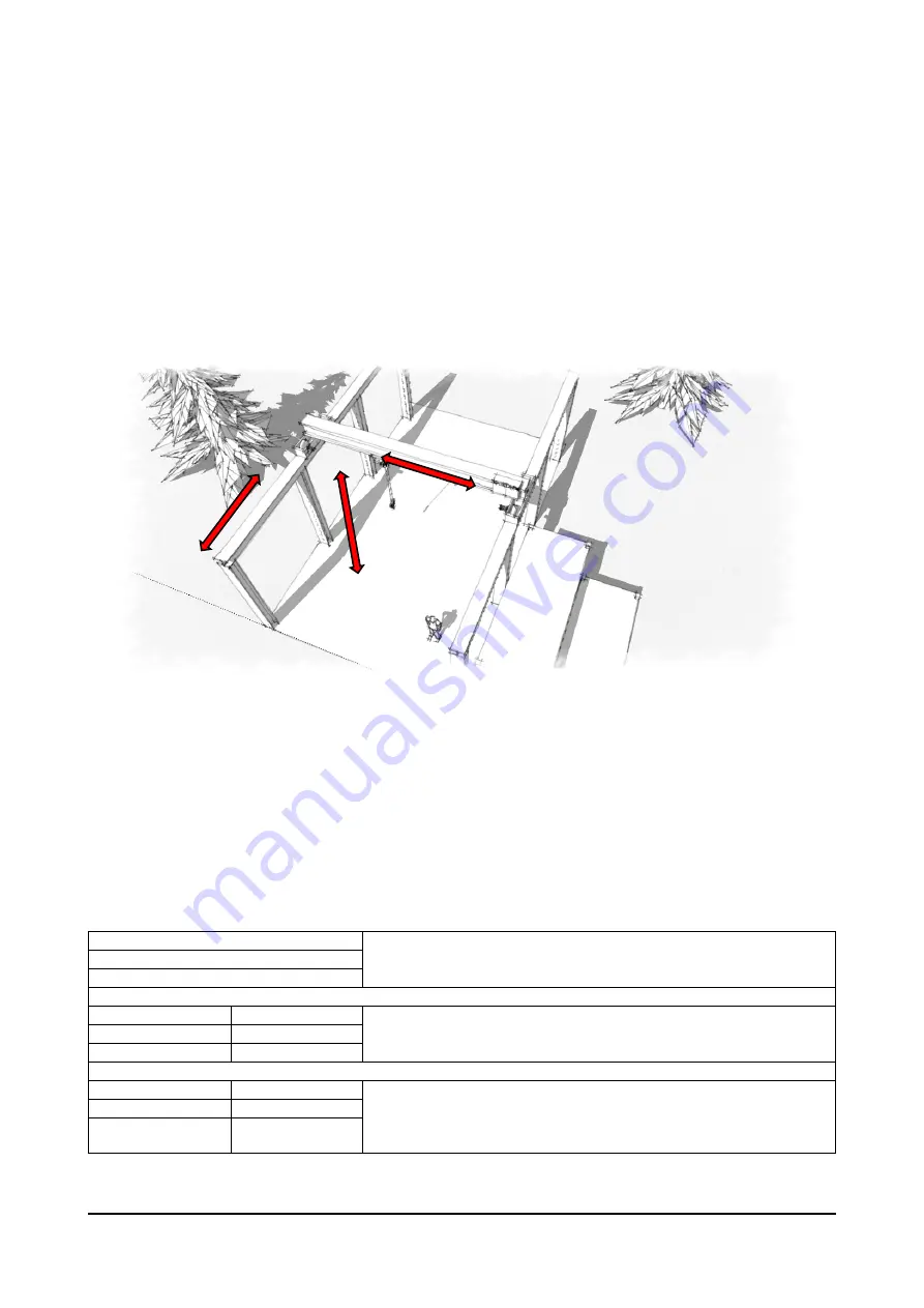
Typical structure of a load handling system: 

A solid structure supports the trolley and its support beam, which moves forward and reverse on parallel 
rails. The trolley moves the lift equipment to the left and right.  

Drive connected to electric motors supply motion: Gantry (forward), Trolley (translation) and Hoist. 
HOIST&CRANE software applied to every drive of each mechanical shaft lets you control and set its speed as 
well as manage all of its main components (joystick, brake, and limit switch) without having to use an external 
PLC. 
You can control and run multiple synchronized motors by using the Electric Shaft or Helper functions.  The 
drives communicate with each other by means of these functions, coordinating system movements and 
management. The type is configured with the &C SERVICE\Movement type IPA11002 parameter, and 
includes: 
 

Hoist 

Drives used individually. 

Gantry 
Trolley 
 
Hoist-ELS-VM 

Hoist-ELS 

Drives connected via FastLink. 
In electric shaft, the movement of drives is controlled in position. 
See ELS chapter for more information. 

Gantry-ELS-VM 

Gantry-ELS 

Trolley -ELS-VM 

Trolley-ELS 

  
Hoist-HL-M 

Hoist-HL-S 

Drives connected via FastLink. 
In Helper(HL) the slave(S) drive follows the torque reference 
generated by master(M) drive. 
See HELPER chapter for more information. 

Gantry-HL-M 

Gantry-HL-S 

Trolley-HL-M 

Trolley-HL-S 

Hoist 

Trolley 

Gantry 

Summary of Contents for ADV200 ASY

Page 1: ...ADV200 HC English Instruction manual ...

Page 2: ...uct functioning period Gefran S p A has the right to modify products data and dimensions without notice The data can only be used for the product description and they can not be understood as legally stated properties All rights reserved Revisions Date Author Description of changes V 0 00 25 February 2015 DLG BNM V 0 01 9 March 2015 DLG BNM BRI changes on pages 4 6 13 16 15 31 36 38 e 40 V 1 0 22 ...

Page 3: ...WAY 26 26 10 ANTI IMPACT 29 26 11 ELS 31 26 12 HELPER 35 26 13 DIGITAL INPUTS 38 26 14 DIGITAL OUTPUTS 39 26 15 ANALOG INPUTS 40 26 16 ALARM CONFIG 40 26 17 FIRMWARE 43 4 1 ALARMS 43 4 2 COMMISSIONING PROCEDURE 44 4 2 1 General information 44 4 2 2 Initial operations 44 4 2 3 Drive parameters managed by the application 44 4 2 4 Essential steps for drive configuration 45 4 2 5 Procedure for manual ...

Page 4: ...ive hardware and software version V f FOC OL FOC CL ADV200 ASY 7 2 7 or later ADV200 SYN 7 2 7 or later NO NO and to its optional cards for acquisition from encoder and expansion of inputs ADV200 FP Manual menu 26 APPLICATIONS On ADV200 HC models the HC application installs by default on the APPLICATIONS APPLICATION 1 menu and replaces the PID application The parameters list is shown in chapter 4 ...

Page 5: ...its speed as well as manage all of its main components joystick brake and limit switch without having to use an external PLC You can control and run multiple synchronized motors by using the Electric Shaft or Helper functions The drives communicate with each other by means of these functions coordinating system movements and management The type is configured with the C SERVICE Movement type IPA110...

Page 6: ...ss of the type of fieldbus used The following example shows a typical configuration of the digital inputs and outputs of the drive with the optional EXP IO D6A4R1 ADV expansion card and the optional encoder for applications requiring a single drive for each mechanical shaft This configuration lets you connect a joystick button panel for movement commands brake feedback management limit switch sens...

Page 7: ...lot 2 Encoder Slot 1 I O 9 10 13 11 14 12 IS1 7 8 FWD Enable REV MultiSpeed 1 MultiSpeed 2 Antiimpact Limit switch Brake fbk Reset Jstk zero pos EXP DE I1R1F2 ADV VE S5 0VE C5 A IN 21 A IN 22 B IN 23 B IN 24 EXP IO D6A4R1 ADV Dig In 1X 71 Dig In 2X 72 Dig In 3X 73 Dig In 4X 74 COM DI C7 10V 10V Dig In E Dig In 1 Dig In 2 Dig In 3 Dig In 4 Dig In 5 0V An Out 1 Rope lenght An In 1 Rope lenght data f...

Page 8: ... open drive enabled 4 ALARM Active alarm 5 Limit switch Limit switch tripped 6 RUN cmd Ctrl COMMAND CONTROL function ON 7 RUN spd up HOIST SPEED UP function ON 8 RUN pwr up SPEED UP function ON 9 RUN low speed LOW SPEED ZONE function ON 10 RUN anti sway ANTI SWAY function ON 11 RUN antiImpact ANTI IMPACT function ON 12 RUN align ALIGNEMENT function ON 26 01 02 12002 Movement type mon ENUM R Displa...

Page 9: ...26 01 15 12030 OL1 mon BOOL R Monitor limit 1 exceeded for Over Load function 26 01 16 12032 OL2 mon BOOL R Monitor limit 2 exceeded for Over Load function 26 01 17 12034 Anti Impact mon BOOL R Monitor limit exceeded for Anti Impact function 26 01 18 12036 LSZ mon BOOL R Monitor indicates entry in speed reduction zone set in Low Speed Zone function 26 01 19 12038 Limit switch FWD mon BOOL R Limit ...

Page 10: ...ing table Digital Inputs Direction State FWD REV FWD cmd src IPA11152 X START FWD REV cmd src IPA11154 X START REV La ricezione contemporanea di entrambi i comandi FWD REV genera l allarme JOYSTICK If Jstk Speed Type is set as Digital 2 digital inputs set via Multi spd 1 src and Multi spd 2 src let you choose 4 possible speed references CMD SPEED according to the following table Digital Inputs Spe...

Page 11: ...ce digital or analog 0 Digital Speed reference depends on value set in CMD SPEED Speed 1 Speed 2 Speed 3 Speed 4 parameters and on commands assigned to digital inputs set as DIGITAL INPUT Multi speed 1 src and Multi speed 2 src 1 Analog Speed reference depends on analog input set via ANALOG INPUT Speed ref src 26 02 04 11064 Jstk zero position BOOL Off R W Enable check of joystick Zero position 26...

Page 12: ...02 12 11192 Measure 1 m FLOAT 0 0 1000 R W During the procedure for defining rope length you are asked to enter the measured length in this parameter for details see ROPE LENGTH DEFINITION PROCEDURE This parameter can be changed ONLY in this procedure 26 02 13 11198 Known position m FLOAT 0 0 1000 R W During the rope length definition procedure you will be asked to enter a known position in this p...

Page 13: ...ise there is no action 3 This is done to prevent false contacts or accidental movements of the joystick button panel from causing unwanted actions The action triggered by the command is kept for a minimum time equal to FWD REV cmd keeping Therefore if you release the command before the time has expired the action will be kept until time 1 has expired on the other hand if you release the command af...

Page 14: ... Description UM Type Def Min Max ACCESS 26 03 01 11012 FWD cmd keeping ms FLOAT 0 0 5000 R W Command keeping time in FWD direction 26 03 02 11014 REV cmd keeping ms FLOAT 0 0 5000 R W Command keeping time in REV direction 26 03 03 11034 Min time cmd jstk ms FLOAT 10 0 1000 R W Minimum keeping time of a command beyond which the command is executed 26 03 04 11100 Zero crossing BOOL Off R W Enabling ...

Page 15: ...004 Speed 1 rpm FLOAT 200 0 6000 R W Speed reference 1 26 04 02 11006 Speed 2 rpm FLOAT 400 0 6000 R W Speed reference 2 26 04 03 11010 Speed 3 rpm FLOAT 1000 0 6000 R W Speed reference 3 26 04 04 11054 Speed 4 rpm FLOAT 2000 0 6000 R W Speed reference 4 26 04 05 11084 FWD Acc time s INT 2 0 01 1000 R W Acceleration in FWD direction 26 04 06 11092 FWD Dec time s INT 2 0 01 1000 R W Deceleration in...

Page 16: ...ding the speed threshold differentiable in the 2 directions You can also insert a delay time for disabling the drive after brake closing MENU PAR Description UM Type Def Min Max ACCESS 26 05 01 11026 FWD OPEN current thr A FLOAT 1 0 1000 R W Current threshold for brake opening FWD Set this parameter only in control mode V f or FOC OL 26 05 02 11028 FWD OPEN torque thr FLOAT 0 0 200 R W Torque thre...

Page 17: ...OAT 20 0 1000 R W Speed threshold for brake opening REV 26 05 09 11048 REV OPEN speed set rpm FLOAT 50 0 1000 R W Speed threshold for brake opening REV 26 05 10 11050 REV CLOSE speed thr rpm FLOAT 100 1 1000 R W Speed threshold for brake closing REV 26 05 11 11052 OPEN pre torque FLOAT 50 0 200 R W Torque injected at time of brake opening Not active in V f mode 26 05 12 11120 CLOSE delay disable m...

Page 18: ... mode or the torque delivered by the motor drive configured in Flux Vector Close Loop or Flux Vector Open Loop mode is below the Spd up FWD REV thr threshold The test period is divided into 2 phases for 1 3 of the time Spd up Test time does not perform any measurement so that the torque current can stabilize for the next 2 3 of the time torque current is monitored If it stays below the Spd up FWD ...

Page 19: ...omatically causes a decrease in motor speed and an increase in available torque The system is therefore stable Overspeed down A rise in the speed reference beyond the work limit at constant torque may lead to a condition where available motor torque is insufficient to support the load The motor drags speed increases further where available torque is still insufficient The system is therefore unsta...

Page 20: ...sed as the maximum limit when the load descends because additional braking power must be supplied during deceleration the power limit must be set at 50 Note If you use ELS electric shaft configuration The thresholds are set in only on the drive defined as virtual master ELS VM The virtual master receives the load s of each shaft from the slaves The action if the threshold is exceeded must be speci...

Page 21: ...speed Rpm FLOAT 3000 0 6000 R W SPEED UP Speed reference REV used after it is determined that the load is ligh 26 06 07 11080 Spd up Test time ms INT 600 0 10000 R W SPEED UP Duration of test during which it is determined that the torque current delivered absorbed by the motor is below Spd up FWD REV thr ATTENTION If the entered value is too high the test may take longer than necessary and slow th...

Page 22: ...gement of the function and cause a more sudden action Values that are too low cause the function to engage too early and prevent reaching of the target power 26 07 OVERLOAD This function protects the hoist system if you try to handle a load that exceeds system capacity which would damage the mechanism To determine if a load is excessive the system measures the current absorbed by the motor inverte...

Page 23: ... Manual Disabled Closed In the graph shown on previous page parameter ALARM CONFIG OL1 Action is set as Warning and therefore does not interfere with any command to the drive The warning state resets automatically when the value returns within the allowed torque current limits Parameter ALARM CONFIG OL2 ACTION is set as Alarm and therefore forces the drive into alarm and closes the mechanical brak...

Page 24: ...one The Low Speed Zone function if enabled defines a zone in which speed of movement is forced to the value set in the LSZ speed parameter The input in this zone is defined via limit switch software i e by specifying the position in absolute value in the Up sw LS abs pos and Low sw LS abs pos parameters For the Hoist movement if a load is attached to the hook and the Measure Load parameter is defi...

Page 25: ...L Off R W Enable Low Speed Zone function 26 08 02 11058 LSZ Speed rpm FLOAT 350 0 6000 R W Speed reference in Low Speed Zone 26 08 03 11112 Up sw LS abs pos FLOAT 1 0 1000 R W Limit switch software absolute position high 26 08 04 11116 Low sw LS abs pos FLOAT 5 0 1000 R W Limit switch software absolute position low ...

Page 26: ...adjustment The above figure shows the movement of the Trolley and of the hoisted load 1 At start the load is delayed compared to Trolley movement and if not properly controlled it will continue to sway with a period depending on rope length The Anti Sway function reduces sway when the swaying load is perpendicular to the trolley 2 When the acceleration phase is done the load is no longer subject t...

Page 27: ...e an On Off switch will be installed on the control panel to command the related digital input of the drive Wiring needed for Anti Sway function To use the Anti Sway function the Hoist motor has to have an encoder that is correctly connected to the command drive An analog or digital connection via fast link with appropriate card is needed to transmit the rope length measurement from the hoist driv...

Page 28: ...ated by the command on the related digital input DIGITAL INPUTS menu Anti Sway src Dig inp Activation deactivation only in Stop If movement starts with AntiSway engaged function stays on until movement stops brake closing 26 09 03 11108 Rope length src ENUM FL Fwd 1 mon R W Analog input to receive rope length measurement required for Anti sway function between Hoist drive and Gantry Trolley 26 09 ...

Page 29: ...de or in current drives configured in V f mode greater than AI Thr is detected during operation the programmed action is commanded The action to be taken if thresholds is exceeded is specified in the Al time and Al Action parameters on the ALARM CONFIG menu Note If you use ELS electric shaft configuration La soglia viene impostata in sul solo drive definito come master virtuale ELS VM The virtual ...

Page 30: ...nction activation command is received from operator 26 10 03 11020 AI Thr FLOAT 50 0 200 R W Impact is identified when during a movement current or torque increases instantaneously by a percentage equal to or greater than this parameter In V f mode the parameter is a of nominal current of the motor In FOC CL or FOC OL mode the AI Thr parameter is a of nominal torque of the motor The Anti Impact fu...

Page 31: ...coders The system is divided into 3 blocks see ELS Control figure Command Virtual Master Management Follower Regulator Figura ELS Control Command Block Receives movement commands FWD and REV and the speed reference from digital or analog input In Electric Shaft function Follower command activated the Command block is active only on the drive defined as Virtual Master for example H C SERVICE Moveme...

Page 32: ...ared to the position generated by the encoder then an error is generated that consequently changes the speed reference The position error is managed by a PI regulator with limitation of output value There is a maximum threshold of the position error beyond which you can activate a Warning or an Alarm and the related consequent activity The block manages the initial positioning function which allow...

Page 33: ...4V 0V24 Slot 2 Encoder Slot 3 Fast Link Slot 1 I O 9 10 13 11 14 12 IS1 7 8 FWD Enable REV MultiSpeed 1 MultiSpeed 2 ELS follow Limit switch Brake fbk ELS align Jstk zero pos EXP DE I1R1F2 ADV VE S5 0VE C5 A IN 21 A IN 22 B IN 23 B IN 24 EXP IO D6A4R1 ADV Dig In 1X 71 Dig In 2X 72 Dig In 3X 73 Dig In 4X 74 COM DI C7 10V 10V Dig In E Dig In 1 Dig In 2 Dig In 3 Dig In 4 Dig In 5 0V 4 1 C1 2 S1 3 S1 ...

Page 34: ...UTS menu K1M F L1 U L2 V L3 W C BR1 Internal BU available up to 55KW D BR2 LR3 Size 160KW L1 L2 L3 PE ADV200 HC Relay 1 Fan Relay 2 R11 R14 24V 0V24 Drive OK Brake Command To auxiliary circuits R21 R24 Braking Resistor C2 IC1 Keypad RS 485 C3 S3 IS2 IC2 24V 0V24 Slot 2 Encoder Slot 3 Fast Link Slot 1 I O 9 10 13 11 14 12 IS1 7 8 Enable ELS follow Limit switch Brake fbk ELS align EXP DE I1R1F2 ADV ...

Page 35: ...erences sent by master block 1 Follow Drive follows commands and references sent by master block 26 12 HELPER Helper HL configuration allows a group of drives maximum of 4 to work with a torque limit on the same mechanical shaft The torque reference is generated by the master drive M which receives movement commands FWD REV and the speed reference from digital or analog input and sends the torque ...

Page 36: ...Encoder Slot 3 Fast Link Slot 1 I O 9 10 13 11 14 12 IS1 7 8 FWD Enable REV MultiSpeed 1 MultiSpeed 2 Antiimpact Limit switch Brake fbk Reset Jstk zero pos EXP DE I1R1F2 ADV VE S5 0VE C5 A IN 21 A IN 22 B IN 23 B IN 24 EXP IO D6A4R1 ADV Dig In 1X 71 Dig In 2X 72 Dig In 3X 73 Dig In 4X 74 COM DI C7 10V 10V Dig In E Dig In 1 Dig In 2 Dig In 3 Dig In 4 Dig In 5 0V 4 1 C1 2 S1 3 S1 5 6 C1 0V Machine G...

Page 37: ...es configured as HL S Inversion of torque reference K1M F L1 U L2 V L3 W C BR1 Internal BU available up to 55KW D BR2 LR3 Size 160KW L1 L2 L3 PE ADV200 HC Relay 1 Fan Relay 2 R11 R14 24V 0V24 Drive OK Brake Command To auxiliary circuits R21 R24 Braking Resistor C2 IC1 Keypad RS 485 C3 S3 IS2 IC2 24V 0V24 Slot 2 Encoder Slot 3 Fast Link Slot 1 I O 9 10 13 11 14 12 IS1 7 8 Enable EXP DE I1R1F2 ADV V...

Page 38: ...act 26 13 07 11164 Limit switch src ENUM Dig inp2X R W Digital input for limit switch contacts 26 13 08 11166 Brake fbk src ENUM Dig inp3X R W Digital input for brake feedback 26 13 09 11168 ELS src ENUM Dig inp4X R W Digital input to activate following Input to be set only on drives configured as ELS VM ELS 26 13 10 11180 Reset src ENUM Dig inp5X R W Digital input for Reset alarms command 26 13 1...

Page 39: ...ignal Anti Impact function active 26 14 02 11176 Brake cmd dest ENUM Pad 1 R W Digital output to control brake contactor 26 14 03 11182 Hoist Spd up dest ENUM Null R W Digital output to signal Hoist speed up active 26 14 04 11184 Power Spd up dest ENUM Null R W Digital output to signal Power speed up active 26 14 05 11186 Low Spd Zone dest ENUM Null R W Digital output to signal handling in Low Spe...

Page 40: ...ke fbk action ENUM Alarm R W Action to be taken if brake feedback does not match command within time set in Brake fbk time 26 16 03 11086 Jstk time ms FLOAT 400 0 10000 R W Maximum allowed time for reception of multiple commands from joystick If after the set time the software detects multiple commands ex FWD REV the action provided in Jstk action is activated 26 16 04 11088 Jstk action ENUM Alarm...

Page 41: ...on Action on drive Action on brake Warning Alarm Warning X Automatic when value returns within limits Normal operation Warning Warning Spd Warning Spd X Freezes deceleration ramp Alarm Rst X Automatic at brake close STOP in ramp commanded Alarm Rst Alarm X Manual Disabled Alarm 26 16 11 11140 Alarm dec time ms FLOAT 1000 0 10000 R W Deceleration time if an alarm trips 26 16 12 11206 ELS pos error ...

Page 42: ... the Slave brake time or Slave enable time parameters are not respected 26 16 18 11224 HL error time ms INT 500 0 10000 R W Parameter to be set only on drives configured as ELS VM If torque error between HL M shaft and HL S drive exceeds HL torque error value for a time exceeding HL error time the action programmed in HL Action is activated 26 16 19 11226 HL torque error FLOAT 10 0 150 R W Paramet...

Page 43: ...ke fbk time parameter OVERLOAD 1 Overload detected Check load weight or setting of OVERLOAD function parameters OVERLOAD 2 Overload detected Check load weight or setting of OVERLOAD function parameters IMPACT Impact detected Check if load has struck an obstacle or check setting of ANTI IMPACT function parameters LIMIT SWITCH Limit switch tripped You can move only in the direction opposite that of ...

Page 44: ... then a Drive reset command Run the guided startup operation which proposes a procedure for rapid commissioning of the drive with a minimum number of settings For customized advanced commissioning you have to use the individual parameters for the functions required To do this see the procedure described in chapter 7 1 1 Guided startup of the manual Rapid installation guide ADV200 QS Use stand stil...

Page 45: ...set src ENUM null 23 08 05 5712 FL N Fwd slave chg INT 0 23 08 06 5714 FL fault enable src ENUM One 23 08 02 5818 FL bidirectional BOOL Enable 23 08 03 5820 FL N of slave INT 1 23 08 11 5830 FL Rev 1 src ENUM Pad 7 23 08 12 5832 FL Rev 2 src ENUM Pad 8 4 2 4 Essential steps for drive configuration See the relative chapters for specific brake and function settings Descrizione Menu Parametro IPA 1 L...

Page 46: ...tch 26 02 08 11142 11 Specify multispeeds of commands received If digital JSTK SPEED TYPE IPA 11062 set all 4 parameters If analog JSTK SPEED TYPE IPA 11062 set only first parameter SPEED 1 IPA 11004 as maximum commanded speed HOIST CRANE CMD SPEED Speed 1 4 26 04 01 04 11004 11006 11010 11054 Set only for drives ELS and HL Configure FastLink address on each drive setting drive ELS VM or HL M to 1...

Page 47: ...iables are vTorque_Nm and vSpeed_Rad_sec see chapter List of parameters monitorable with SoftScope SW oscilloscope for more information If system inertia is dominated by the constant the hoisted load is not important it can also be zero The magenta line shows speed the blue line shows torque A rise positive speed and a descent are recorded The torque line clearly shows the gap between acceleration...

Page 48: ...s an oscillation is the time the hook takes to swing and return to starting position Calculate the period of oscillation T measurement in seconds 10 Calculate rope length with the formula L g T 2π 2 Where L rope length in meters g gravity constant 9 81 m s2 T period of oscillation Enter the result in the H C SERVICE known position parameter when requested during the rope length definition procedur...

Page 49: ...re depending on whether the mechanical ratio of motor rpm distance is known or not PROCEDURE for known conversion ratio Write coefficient of ratio motor rpm distance in H C SERVICE mpr parameter IPA11148 Bring hook to a known position and write distance expressed in meters between hook and rope winder drum or from pulleys if present C in H C SERVICE Known position parameter IPA 11198 This operatio...

Page 50: ...e the trolley or beam as far as possible and bring the H C SERVICE Define length parameter IPA 11146 to Measure 1 Measure A and make a note of the distance between the hook and the ground Raise the hook by about 1 meter Measure B and enter the shift Measure 1 B A in the H C SERVICE Measure 1 parameter IPA 11192 This operation lets you determine the ratio between motor rpms and actual shift on the ...

Page 51: ...tance is not known see chapter Calculation of rope length and enter the result in the known position parameter In the H C SERVICE Measure load parameter IPA11200 enter the distance between the hook groove and the hypothetical center of gravity of the load D Save and reset the drives Movements of the hook trolley or beam with the drive off will cause misalignment between the real position and the p...

Page 52: ... v LimSwitchREV_mon Limit switch REV mon 12040 MONITOR vRifSpeed_mon Speed ref mon 12042 MONITOR vPosition Position mon 12040 MONITOR vELS_align ELS align 12042 MONITOR pHoist_drive Movement type 11002 H C SERVICE pDecoding Jstk Decoding 11060 H C SERVICE pAD_Sel Jstk Speed Type 11062 H C SERVICE pJpos_Z_cmd Jstk zero position 11064 H C SERVICE pInversion Rotate inversion 11074 H C SERVICE pBrake ...

Page 53: ... pThr_Speed_FWD Spd up FWD speed 11072 HOIST SPEED UP pThr_Torque_REV Spd up REV thr 11076 HOIST SPEED UP pThr_Speed_REV Spd up REV speed 11078 HOIST SPEED UP pTime_Speed_ctrl Spd up Test time 11080 HOIST SPEED UP pThr_Speed_ctrl Spd up test speed 11082 HOIST SPEED UP pRef_Pwr_FWD PWR UP FWD pwr ref 11102 HOIST SPEED UP pRef_Pwr_REV PWR UP REV pwr ref 11170 HOIST SPEED UP pKp PWR UP gain 11218 HOI...

Page 54: ... 11184 DIGITAL OUTPUT pLSZ_dest Low Spd Zone dest 11186 DIGITAL OUTPUT pOL_Ctrl_dest Over Load dest 1 11188 DIGITAL OUTPUT pOL2_Ctrl_dest Over Load dest 2 11190 DIGITAL OUTPUT pEndLimit_dest Limit switch dest 11202 DIGITAL OUTPUT pAS_dest Anti sway dest 11204 DIGITAL OUTPUT pSpeedRef_src Speed ref src 11104 ANALOG INPUT pBrake_CmdFdk_dly Brake fbk time 11022 ALARM CONFIG pBRAKE_Action Brake fbk ac...

Page 55: ...ADV200 HC Manual Page 55 of 55 Signal Corresponding parameter IPA MENU vAlarm_state Alarm state 12054 ALARM CONFIG ...

Reviews: