background image

September 2007

3-8

Startup & Operation

Changing the 4-20 mA 
Analog Output Range

The XMO2 

Calibration Sheet

 shipped with the unit lists the 4-20 mA 

analog output range that was set at the factory. To change this range 
using RS232 digital communication, perform the following steps:

1.

If the XMO2 is not set up for 

Easy Menu Entry

, enter the XMO2 

Basic Menu

 by slowly keying in 

[Shift]+[1]

 or 

[Enter], [1], [2], [3]

Refer to the menu map in Figure C-1 on page C-1 for the options 
available in this menu.

2.

Press 

[N]

 repeatedly until the following display appears:

Note:

The 

low input value

 is the %O

2

 in the sample gas that will 

generate an analog output current of 4.00 mA.

3.

At the above screen, do one of the following:

Press 

[Y]

 or 

[Enter]

 to accept the current low input value (0.00 in 

the above example). Then, go to Step 5.

Use the numeric keys to enter a new low input value (5.00 in 
the example that follows). Then, go to Step 4.

4.

If you entered a new low input value:

5.

Continue the procedure as follows:

Note:

The 

high input value

 is the %O

2

 in the sample gas that will 

generate an analog output current of 20.00 mA.
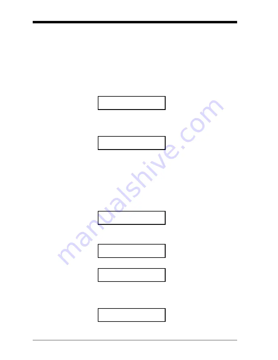
BASIC MENU

Press 

[Y]

 or 

[Enter]

 to set the low 

(4 mA) input value.

Set Low Input Value?

mA Output 4 mA Value

%O2 [0.00]:

mA Output 4 mA Value

Press 

[Y]

 or 

[Enter]

 to accept the 

new low (4 mA) input value.

%O2 [0.00]:5.00

BASIC MENU

Press 

[N]

 to move to the next 

Basic Menu

 option.

Set Low Input Value?

BASIC MENU

Press 

[Y]

 or 

[Enter]

 to set the high 

(20 mA) input value.

Set High Input Value?

mA Output 20 mA Value

%O2 [100.00]:

Summary of Contents for XMO2

Page 1: ...User s Manual 910 141A5 September 2007 Attention This manual should be used for XMO2 units with the Terminal User Program Option D 1 or 2 only For XMO2 units with the IDM User Program Option D 3 or 4 manual number 910 141B or a later revision must be used ...

Page 2: ...ose and warranties arising from course of dealing or usage or trade Return Policy If a GE Sensing Inc instrument malfunctions within the warranty period the following procedure must be completed 1 Notify GE giving full details of the problem and provide the model number and serial number of the instrument If the nature of the problem indicates the need for factory service GE will issue a RETURN AU...

Page 3: ...tem 2 3 Wiring the XMO2 Transmitter 2 4 CE Mark Requirements 2 4 Grounding the XMO2 Transmitter 2 5 Cable Specifications 2 6 Accessing Terminal Block TB1 2 7 Wiring the Signal Connections 2 8 Connecting to Other Devices 2 9 The PS5R C24 Power Supply 2 9 TMO2D Display 2 10 LDP Display 2 10 XDP Display 2 10 Moisture Image Monitor Series Analyzers 2 10 System 1 Analyzer 2 10 Chapter 3 Startup Operati...

Page 4: ...d Calibration 4 7 Setup 4 7 Zero Gas Pushbutton Calibration 4 7 Span Gas Pushbutton Calibration 4 8 Two Gas RS232 Communication Calibration 4 8 Chapter 5 Basic Programming Introduction 5 1 Establishing the RS232 Communication Link 5 2 Programming Keystrokes 5 3 Menu Navigation 5 3 Entering the Basic Menu 5 4 Basic Menu Options 5 4 QUICK OFFSET Option 5 5 VIEW OFFSET Option 5 6 QUICK ZERO Option 5 ...

Page 5: ... Option 6 18 DRIFTCAL HANDLER Option 6 23 DONE Option 6 35 CALIBRATE RECORDER Menu 6 36 TEST INPUTS Menu 6 37 O2 INPUT Option 6 37 COMP INPUT Option 6 38 PRESSURE INPUT Option 6 38 RAW BRIDGE INPUT Option 6 39 OFFSET INPUT Option 6 39 TEMPERATURE INPUT Option 6 40 BRIDGE POWER INPUT Option 6 40 ANALOG GROUND INPUT Option 6 41 DONE Option 6 41 TEST RECORDER Menu 6 42 ENTER mA Option 6 42 ENTER UNIT...

Page 6: ...TER Option 7 12 GAS mV EXP FILTER Option 7 16 COMP mV EXP FILTER Option 7 17 DRIFTCAL HANDLER Option 7 17 DONE Option 7 20 CALIBRATE RECORDER Menu 7 20 SET ERROR HANDLING Menu 7 21 TERMINAL Option 7 22 mA OUTPUT Option 7 28 DONE Option 7 29 ERASE RAM Menu 7 29 RESUME Menu 7 30 Chapter 8 Specifications and Factory Data Performance Specifications 8 1 Functional Specifications 8 2 Physical Specificat...

Page 7: ... 3 RS232 Digital Output Cables B 4 Digital PCB Assembly B 5 Digital PCB Schematic sheet 1 B 6 Digital PCB Schematic sheet 2 B 7 Analog PCB Assembly B 8 Analog PCB Schematic sheet 1 B 9 Analog PCB Schematic sheet 2 B 10 Appendix C Menu Maps Basic All Submenus and Options C 1 General Cal System System Mode Gas Curve Background Grid C 2 General Calibrate System Pressure Curve Pressure Grid C 3 Genera...

Page 8: ...Chapter 1 ...

Page 9: ...Features and Capabilities Introduction 1 1 Basic Features 1 1 Theory of Operation 1 3 System Components 1 6 ...

Page 10: ...XMO2 provides automatic oxygen signal compensation for background gas composition and or pressure variations In addition the XMO2 is equipped with Fast Response software real time error detection and push button field calibration The XMO2 Transmitter offers several unique design features Ultra stable thermistors and a measuring cell that is temperature controlled at 45 C 113 F provide excellent ze...

Page 11: ...E cables An RS232 serial communications interface and a multi level menu driven User Program provide a convenient means for calibrating and programming the XMO2 Internal software algorithms along with user programmed calibration data provide compensation of the oxygen signal for background gas composition atmospheric pressure or both background gas composition and atmospheric pressure GE s proprie...

Page 12: ... known as a magnetic wind The intensity of this magnetic wind depends on the concentration of oxygen in the gas mixture Figure 1 1 below shows a flow schematic for the XMO2 measuring cell Permanent magnets within the cell create a magnetic field while the cell temperature is controlled at 45 C 113 F to maintain thermal equilibrium In addition the cell contains two pairs of highly stable glass coat...

Page 13: ...ecrease This slight gradient in sample gas pressure causes the sample gas to flow outward from the center of the magnetic field and over the thermistors As a result the inner wind generating thermistors decrease in temperature as they lose heat to the magnetic wind This causes a temperature gradient between the cooler inner thermistors and the warmer outer thermistors Figure 1 3 on page 1 5 shows ...

Page 14: ...a function of the thermal properties of the background gas Therefore this power fluctuation provides a signal that is related to the thermal conductivity of the background gas That signal is then used to reduce the effects of the background gas variation on the oxygen span point measurement In addition to maintaining a constant oxygen bridge temperature the XMO2 microprocessor compensates for any ...

Page 15: ...so be performed via this interface All XMO2 transmitters include a 10 ft 3 m 4 conductor cable for connecting the power input and the 4 20 mA analog output Optional XMO2 accessories available from GE include power analog output cable lengths of up to 450 ft 137 m 24 VDC power supply Model PS5R C24 3 conductor cable with a DB9 male or female or DB25 male or female connector for connecting the XMO2 ...

Page 16: ...ement cell at an operating temperature of 45 C 113 F An optional 60 140 F or 70 C 158 F cell operating temperature is available upon request Note The 60 140 F or 70 C 158 F cell operating temperatures should be selected only when necessary as the higher cell operating temperature results in reduced sensitivity Inlet Flame Arrestor Flame Arrestor Outlet ...

Page 17: ...IMPORTANT ATEX compliance with EN 50104 requires both Fast Response calibration of the XMO2 transmitter Pressure Compensation of the XMO2 or constant control of the sample system pressure Long Cables optional GE provides a standard 10 ft 3 m 4 conductor color coded cable with each XMO2 to connect to the power input and the analog output Optional cables are available in lengths up to 450 ft 137 m a...

Page 18: ...Chapter 2 ...

Page 19: ...Installation Introduction 2 1 Installing the XMO2 Transmitter 2 1 Installing the Sample System 2 2 Wiring the XMO2 Transmitter 2 4 Connecting to Other Devices 2 9 ...

Page 20: ...lates and is delivered at atmospheric pressure a temperature no greater than 40 C 104 F and a flow rate of approximately 1 0 SCFH 500 cc min A typical sample system for the XMO2 might include an inlet gas flow regulating needle valve a sample gas flow meter and a pressure gauge Note Because factory calibration of the XMO2 is done at atmospheric pressure and at a flow rate of 1 0 SCFH operation of ...

Page 21: ...the XMO2 transmitter and all necessary components and plumbing Several standard sample systems are available and custom designed sample systems can be built to your exact specifications A Basic System Figure 2 1 below shows a basic sample system dwg 732 164 that has been designed for use with the XMO2 transmitter Figure 2 1 A Basic XMO2 Sample System dwg 732 164 ...

Page 22: ...n the range of 20 to 40 C 4 to 104 F IMPORTANT For locations where the ambient temperature falls below 20 C 4 F install the sample system in a heated enclosure 2 Using the mounting holes provided fasten the sample system to a convenient vertical surface The system must be installed in an orientation that keeps the XMO2 transmitter upright and level to within 15 3 After the sample system has been m...

Page 23: ... Union s Low Voltage Directive 73 23 EEC the XMO2 requires an external power disconnect device such as a switch or circuit breaker The disconnect device must be marked as such clearly visible directly accessible and located within 1 8 m 6 ft of the unit Note If the instructions above are followed the unit will comply with the Low Voltage Directive 73 23 EEC Table 2 1 Wiring Modifications for EMC C...

Page 24: ...rd PCB inside the enclosure To perform this task proceed as follows 1 Use Figure 2 2 below to locate the desired ground screw 2 If the internal ground screw will be used remove the cover and the printed circuit board PCB from the XMO2 enclosure 3 Connect a suitable wire to the ground screw and terminate it at a nearby earth ground connection 4 If the PCB was removed reinstall it now Figure 2 2 Loc...

Page 25: ...cable is available in standard lengths of 6 ft and 12 ft See the EIA RS Serial Communications booklet GE document 916 054 for a more detailed discussion of RS232 wiring Note See Figure B 4 on page B 4 for detailed drawings of the standard GE cables described above Table 2 2 GE 4 Wire XMO2 Cable P N X4 L Lead Color AWG Terminal 24 VDC Line Red 22 TB1 1 24 VDC Return Black 22 TB1 2 4 20 mA White 22 ...

Page 26: ... this terminal block loosen the locking set screw and remove the cover from the transmitter Then refer to Figure 2 3 below for the location and pin designations of terminal block TB1 Caution Do not make any connections to any unused pins on terminal block TB1 Figure 2 3 Terminal Block TB1 Connections Proceed to the next section to begin making connections to terminal block TB1 External Ground Scre...

Page 27: ...nto pin TB1 1 and tighten the screw b Insert the 4 wire cable 24 VDC black lead into pin TB1 2 and tighten the screw 5 Connect the 4 20 mA analog output leads as follows a Insert the 4 wire cable 4 20 mA white lead into pin TB1 3 and tighten the screw b Insert the 4 wire cable 4 20 mA green lead into pin TB1 4 and tighten the screw 6 Connect the optional RS232 digital output leads as follows a Ins...

Page 28: ... analyzer The PS5R C24 Power Supply The GE PS5R C24 power supply converts a 100 240 VAC input to the required 24 VDC output Figure 2 4 below shows the PS5R C24 connections As indicated the AC input Line Neutral and Ground connections are made to the terminals along the bottom of the panel while the DC output 24V and 24V connections are made to the terminals along the top of the panel See the instr...

Page 29: ...input range two SPDT alarm relays rated for 1A 250 VAC and an isolated independently adjustable 4 20 mA analog output The XDP is supplied in an explosion proof enclosure that is rated for Cenelec EEx d IIC T6 approval pending and IP66 with optional gasket See Figure B 3 on page B 3 for an interconnection diagram and refer to the XDP User s Manual 910 204 for details on its operation Moisture Image...

Page 30: ...Chapter 3 ...

Page 31: ...n 3 1 Powering Up the XMO2 Transmitter 3 1 Establishing a Sample Gas Flow 3 1 Analog Output Calibration Options 3 3 Pushbutton Calibration 3 3 RS232 Digital Communication Calibration 3 6 Changing the 4 20 mA Analog Output Range 3 8 ...

Page 32: ...onstant 45 C 113 F operating temperature allow at least 30 minutes for the unit to warm up and reach temperature stability before taking any measurements During this time you can establish a sample gas flow through the system as described in the next section Establishing a Sample Gas Flow Usually the XMO2 transmitter is factory calibrated at a sample gas flow rate of 1 0 SCFH 500 cc min and at atm...

Page 33: ...ted units the XMO2 outlet port must be vented directly to atmosphere with no restrictions by installing all sample system components and tubing upstream of the XMO2 transmitter 4 Take a reading of the XMO2 4 20 mA analog output In some applications pressure changes due to flow rate changes can cause noticeable errors in the oxygen measurement In such cases consider the following corrective measure...

Page 34: ...mplest method for performing an initial field calibration of the XMO2 s 4 20 mA analog output This method requires only a single calibration gas called an offset gas The XMO2 is usually factory programmed for the offset gas pushbutton calibration method The Calibration Sheet shipped with your unit specifies the recommended oxygen level in O2 for the offset gas to be used This is the same offset ga...

Page 35: ...tion cont Figure 3 1 XMO2 Cover Set Screw and PCB To perform the offset gas pushbutton calibration refer to Figure 3 2 below and complete the following steps Figure 3 2 PCB 703 1139 Calibration Switches Circuit Board Set Screw Cover Switch S1 TB1 Switch S3 ...

Page 36: ...sure conditions used for the sample gas and allow the offset gas to flow through the XMO2 for at least three minutes 3 Using the ammeter record the analog output mA value and compare it to the expected value 4 Using Figure 3 2 on page 3 4 as a guide locate the Calibration Pushbutton Switch S3 Depress the Calibration Pushbutton and hold it down for 20 seconds During this time the green light below ...

Page 37: ...nch the appropriate interface software to establish communications with the XMO2 To begin the RS232 digital communication calibration power up the XMO2 When power is first applied the XMO2 performs a series of initialization routines Displays similar to those shown below should appear on your computer screen After displaying the firmware version and testing RAM this takes about 10 seconds the XMO2...

Page 38: ...he menu map in Figure C 1 on page C 1 for the options available in this menu 3 For a one gas offset gas calibration press N repeatedly until the following display appears 4 Note that the display now shows the O2 level as calculated using the factory programmed calibration data listed on your XMO2 Calibration Sheet 5 After the automatic Quick Offset calibration is complete the following display app...

Page 39: ... of 4 00 mA 3 At the above screen do one of the following Press Y or Enter to accept the current low input value 0 00 in the above example Then go to Step 5 Use the numeric keys to enter a new low input value 5 00 in the example that follows Then go to Step 4 4 If you entered a new low input value 5 Continue the procedure as follows Note The high input value is the O2 in the sample gas that will g...

Page 40: ...f you entered a new high input value 8 Complete the procedure as follows The range of the 4 20 mA analog output has now been changed Be sure to revise your XMO2 Calibration Sheet to show the new range For additional information or if programming assistance is required refer to Chapter 5 Basic Programming mA Output 4 mA Value Press Y or Enter to accept the new high 20 mA input value O2 100 00 25 00...

Page 41: ...Chapter 4 ...

Page 42: ...Introduction 4 1 Factory Calibration Procedures 4 1 Enhancing the Factory Calibration 4 2 Required Calibration Materials 4 3 Preparing for Field Calibration 4 3 One Gas Field Calibration 4 5 Two Gas Field Calibration 4 7 ...

Page 43: ...the time of purchase The following standard O2 ranges are available 0 to 1 0 to 25 0 to 2 0 to 50 0 to 5 0 to 100 0 to 10 80 to 100 0 to 21 90 to 100 Pressure compensation is required In addition your XMO2 was calibrated at the factory for the compensation signal specified at the time of purchase The following standard compensation signals are provided Background Gas Compensation the standard fact...

Page 44: ... Drift Curve along with any background gas and or cell pressure compensation data entered at the factory or in the field to update the factory calibration data To maintain the integrity of this process the XMO2 should be recalibrated periodically This is typically done every 1 3 months with a single offset calibration gas depending on the application The optimum recalibration interval depends on s...

Page 45: ...the required pressure and flow rate See Chapter 2 Installation for specific recommendations a multimeter ammeter for a 4 20 mA analog output calibration WARNING Avoid using explosive gas mixtures as your XMO2 calibration gas es Preparing for Field Calibration To prepare the XMO2 for a field calibration refer to Figure 4 1 on page 4 4 and perform the following preliminary steps 1 Turn the power on ...

Page 46: ...irectly below the cover see Figure 4 1 above Figure 4 2 PCB 703 1139 Calibration Switches Caution Switch S2 jumper P6 potentiometer R24 and potentiometer R25 are also located on the XMO2 circuit boards However these items are not used for normal field calibration Never touch these items unless specifically instructed to do so by GE Circuit Board Set Screw Cover Switch S1 TB1 Switch S3 ...

Page 47: ...ate section for instructions Pushbutton Method To perform a pushbutton offset gas field calibration complete the following steps 1 Verify that your XMO2 is configured for a one gas calibration see Chapter 5 Basic Programming for details This is the factory default configuration for all units 2 Using the sample system controls stop the flow of sample gas to the XMO2 inlet port and initiate a flow o...

Page 48: ... option should appear IMPORTANT If the initial Basic Menu option is Quick Zero your XMO2 is configured for a two gas calibration You must change this to a one gas calibration before proceeding see Chapter 6 General Programming for instructions 4 After the automatic Quick Offset calibration is complete continue as follows The XMO2 Quick Offset field calibration is now complete and the display shows...

Page 49: ... The zero and span calibrations can be performed in either order For zero based calibration ranges e g 0 25 we recommend performing the span calibration first For non zero based calibration ranges e g 90 100 we recommend performing the zero calibration first Proceed to the appropriate section to begin the field calibration Zero Gas Pushbutton Calibration To perform a zero gas pushbutton field cali...

Page 50: ...reen light will come back on and the XMO2 has been recalibrated You may now return the XMO2 to normal operation by using the sample system controls to stop the span gas flow and restart the flow of sample gas Note After performing a two gas field calibration you should return the XMO2 to one gas calibration mode See Chapter 6 General Programming for instructions Two Gas RS232 Communication Calibra...

Page 51: ...n procedure as follows The XMO2 two gas field calibration is now complete and the display shows the corrected O2 level You may now return the XMO2 to normal operation by using the sample system controls to stop the span gas flow and restart the flow of sample gas BASIC MENU Press Y or Enter to initiate the span gas calibration Quick Span BASIC MENU This screen appears while the calibration is taki...

Page 52: ...Chapter 5 ...

Page 53: ...Basic Programming Introduction 5 1 Establishing the RS232 Communication Link 5 2 Programming Keystrokes 5 3 Menu Navigation 5 3 Entering the Basic Menu 5 4 Basic Menu Options 5 4 ...

Page 54: ...data Advanced Menu offers problem solving functions to repair the errors diagnosed in the General Menu Data entered into the XMO2 User Program by the user overrides any previously entered data and is retained in memory for several years even if power to the XMO2 is interrupted This chapter provides information on programming the Basic Menu The following specific topics are discussed establish the ...

Page 55: ...ile it is powered up Damage to the system may result 3 Power up the PC and launch the terminal communications software that is provided with your computer s operating system Commonly used programs are Terminal HyperTerminal HyperACCESS SmartTerm etc Note See the documentation that came with your computer for instructions on launching and using your program 4 In the terminal communications software...

Page 56: ...o the next menu option or to clear a numeric entry Selector Keys The and keys are used as selector keys The key is used to step backward through a displayed list of menu options or as a backspace erase key during numeric entry The key is used to step forward through a displayed list of menu options It is equivalent to the N key Data Entry Keys The 0 9 and keys are used to enter numeric values Menu...

Page 57: ...m Basic Menu Options The Basic Menu which is accessed as described on page 5 4 includes eight possible menu options Of the eight possible options a total of 3 5 or 6 can appear at any one time The specific options and when they are available are determined as shown in Table 5 1 below Note DriftCal Handler and the Number of Gases are specified in the General Menu see Chapter 6 General Programming P...

Page 58: ...d on the XMO2 Calibration Sheet Establish the same flow rate and pressure conditions used for the sample gas and allow the offset gas to flow through the XMO2 for at least three minutes 2 Perform the offset gas calibration press N until the following prompt appears Then proceed as follows You may now do one of the following Press N as many times as necessary to select another Basic Menu option The...

Page 59: ...e gas calibration has been selected To use the View Offset option press N until the following prompt appears Then proceed as follows You may now do one of the following Press N as many times as necessary to select another Basic Menu option Then press Y and proceed to the appropriate section for instructions Press N repeatedly until the Resume option appears Then press Y to return to Operate Mode B...

Page 60: ...cified on the XMO2 Calibration Sheet Establish the same flow rate and pressure conditions used for the sample gas and allow the zero gas to flow through the XMO2 for at least three minutes 2 Perform the zero gas calibration press N until the following prompt appears Then proceed as follows You may now do one of the following Press N as many times as necessary to select another Basic Menu option Th...

Page 61: ...cified on the XMO2 Calibration Sheet Establish the same flow rate and pressure conditions used for the sample gas and allow the span gas to flow through the XMO2 for at least three minutes 2 Perform the span gas calibration press N until the following prompt appears Then proceed as follows You may now do one of the following Press N as many times as necessary to select another Basic Menu option Th...

Page 62: ...View Drift Curve option press N until the following prompt appears Then proceed as follows You may now do one of the following Press N as many times as necessary to select another Basic Menu option Then press Y and proceed to the appropriate section for instructions Press N repeatedly until the Resume option appears Then press Y to return to Operate Mode BASIC MENU Press Y or Enter to view the Dri...

Page 63: ...n go to Step 4 Use the numeric keys to enter a new low input value 5 00 in the example that follows Then go to Step 3 3 If you entered a new low input value 4 Complete the procedure as follows You may now do one of the following Press N as many times as necessary to select another Basic Menu option Then press Y and proceed to the appropriate section for instructions Press N repeatedly until the Re...

Page 64: ...to Step 4 Use the numeric keys to enter a new high input value 25 00 in the example that follows Then go to Step 3 3 If you entered a new high input value 4 Complete the procedure as follows You may now do one of the following Press N as many times as necessary to select another Basic Menu option Then press Y and proceed to the appropriate section for instructions Press N repeatedly until the Resu...

Page 65: ... and if a one or two gas calibration has been selected To use the Resume option press N until the following prompt appears You may now do one of the following Press N as many times as necessary to select another Basic Menu option Then press Y and proceed to the appropriate section for instructions Press Y to leave the Basic Menu and return to Operate Mode BASIC MENU Resume ...

Page 66: ...Chapter 6 ...

Page 67: ...g Introduction 6 1 Entering the General Menu 6 2 General Menu Options 6 2 CALIBRATE SYSTEM Menu 6 3 CALIBRATE RECORDER Menu 6 36 TEST INPUTS Menu 6 37 TEST RECORDER Menu 6 42 SET ERROR HANDLING Menu 6 43 RESUME Menu 6 46 ...

Page 68: ...k calibration General Menu provides error diagnostics and factory calibration data entry Advanced Menu offers problem solving functions to repair any errors diagnosed in the General Menu Data entered into the XMO2 User Program overrides any previously entered data and it is retained in memory for several years even if power to the XMO2 is interrupted This chapter provides information on programmin...

Page 69: ...may be accessed via this menu option Calibrate Recorder The default analog output high and low values may be accessed via this menu option Test Inputs For diagnostic purposes various input parameters may be accessed via this menu option Test Recorder For diagnostic purposes the analog output values may be accessed via this menu option Set Error Handling the manner in which the XMO2 responds to var...

Page 70: ...wn in Table 6 1 below Note The background and pressure compensation settings are specified in the System Mode submenu see page 6 4 Refer to Figures C 2 through C 5 in Appendix C Menu Maps and proceed to the appropriate section to program the desired option GENERAL MENU Press N until this prompt appears then press Y or Enter Calibrate System Table 6 1 Available Submenu Options Submenu Option Backgr...

Page 71: ...O2 uses calibration data entered for pressure compensation along with data stored in the drift curve to compensate the oxygen signal Note Pressure compensation can be used only if the XMO2 is provided with an optional atmospheric pressure transducer The next prompt enables the XMO2 to provide background gas compensation of the oxygen signal The XMO2 uses calibration data entered for background gas...

Page 72: ... Mode option in the Calibrate System menu You may now do one of the following Press N as many times as necessary to select another Calibrate System menu option Then press Y and proceed to the appropriate section of this chapter for instructions Press N repeatedly until you reach the Done option of the Calibrate System menu then press Y to return to the top level of the General Menu Calibration Mod...

Page 73: ...pt you can enter the oxygen value for one of the gas curve data points listed on your Calibration Sheet see page 8 6 for a sample calibration sheet Note The gas type displayed in the next prompt is specified in the Select Gas Type option of the Advanced Menu The choices are O2 used as an example in this manual H2 N2 SO2 and CO2 Refer to Chapter 7 Advanced Programming for more details The next prom...

Page 74: ...hat you intend to use The XMO2 displays working as it records the calibration data and then repeats the O2 and Introduce x xx O2 prompts for the number of points specified at the Points prompt This completes the programming of the Gas Curve option and the XMO2 returns to the Calibrate System menu Enter Gas Curve To accept the current value press Y or Enter To change the current value use the numer...

Page 75: ...n appears only if Pressure Compensation is OFF and Background Compensation is ON as specified in the System Mode menu see page 6 4 At the Curves prompt specify the number of calibration data curves to be entered Each curve represents a specific concentration of a particular background gas IMPORTANT The Curves for your unit is listed on its calibration data sheet see page 8 6 for a sample sheet and...

Page 76: ... on the next two pages to continue the programming sequence Note After all data points specified at the Points prompt for the current curve have been entered this sequence is repeated for the next curve After all of the curves specified in the Curves prompt have been entered programming of the Background Grid option is completed and you will be returned to the Calibrate System prompt Curve n To ac...

Page 77: ...meric Entry at the Calibrate Mode prompt and N at the Enter Point prompt the Interpolate Point prompt is used to have the XMO2 perform a linear interpolation to determine the corresponding mV value for the current O2 point Note The XMO2 linear interpolation capability is useful when a data curve is missing one or more of its data points After the XMO2 performs the linear interpolation you are retu...

Page 78: ...nt prompt the Interpolate Point prompt is used to have the XMO2 perform a linear interpolation to determine the corresponding mV value for the current O2 point Note The XMO2 linear interpolation capability is useful when you do not have a calibration gas with the required oxygen background gas composition for a given point The XMO2 displays working as it records the calibration data and then retur...

Page 79: ...r Calibration Sheet see page 8 6 for a sample calibration sheet Note The pressure units displayed in the next prompt are specified in the Select Pressure Type option of the Advanced Menu The choices are Pres generic mmHg used as an example in this manual PSIa and kPa Refer to Chapter 7 Advanced Programming for more details The next prompt to appear depends on whether you selected Numeric Entry or ...

Page 80: ...se The XMO2 displays working as it records the calibration data and then repeats the mmHg and Introduce xxx x mmHg prompts for the number of points specified at the Points prompt This completes the programming of the Pressure Curve option and the XMO2 returns to the Calibrate System menu Enter Pressure Curve To accept the current value press Y or Enter To change the current value use the numeric k...

Page 81: ...allows you to enter a fixed pressure for one of the curves in the pressure grid Note The pressure units displayed in the next prompt are specified in the Select Pressure Type option of the Advanced Menu The choices are Pres generic mmHg used as an example in this manual PSIa and kPa Refer to Chapter 7 Advanced Programming for more details The Curve n prompt repeats until the total number of curves...

Page 82: ...s at the Calibrate Mode prompt on page 6 5 Proceed to one of the sections on the following two pages to continue the programming sequence Note After all data points specified at the Points prompt for the current curve have been entered this sequence is repeated for the next curve After all of the curves specified in the Curves prompt have been entered programming of the Pressure Grid option is com...

Page 83: ...ic Entry and N If you selected Numeric Entry at the Calibrate Mode prompt and N at the Enter Point prompt the Interpolate Point prompt is used to have the XMO2 perform a linear interpolation to determine the corresponding mV value for the current O2 and pressure values Note The XMO2 linear interpolation capability is useful when a data curve is missing one or more of its data points After the XMO2...

Page 84: ... the Interpolate Point prompt is used to have the XMO2 perform a linear interpolation to determine the corresponding mV value for the current O2 and pressure values Note The XMO2 linear interpolation capability is useful when you do not have a calibration gas with the required oxygen concentration and pressure for a given point The XMO2 displays working as it records the calibration data and then ...

Page 85: ...o be entered Each grid represents a specific pressure The Grid n prompt allows you to enter a fixed pressure for one of the grids in the pressure background grid Note The pressure units displayed in the next prompt are specified in the Select Pressure Type option of the Advanced Menu The choices are Pres generic mmHg used as an example in this manual PSIa and kPa Refer to Chapter 7 Advanced Progra...

Page 86: ...cified at the Curves prompt have been entered After all the N2 values have been entered the Points prompt lets you specify the total number of data points to be entered for each curve of the current pressure grid The Point n prompt lets you enter the oxygen for one of the data points on the calibration curves for the current grid Note The gas type displayed in the next prompt is specified in the S...

Page 87: ...nts prompt for the current curve have been entered this sequence is repeated for the next curve After all of the curves specified in the Curves prompt have been entered the programming of the current Pressure Grid is completed and you will be returned to the Curves prompt to program the next grid Numeric Entry Y enter tabulated mV value Numeric Entry N XMO2 interpolates mV value Introduce Gases Y ...

Page 88: ... used to have the XMO2 perform a linear interpolation to determine the corresponding mV value for the current O2 N2 pressure values Note The XMO2 linear interpolation capability is useful when a data curve is missing one or more of its data points After the XMO2 performs the linear interpolation you are returned to the Enter Point prompt on page 6 20 x xx O2 Curve n xxx x mmHg To accept the curren...

Page 89: ...pt the Interpolate Point prompt is used to have the XMO2 perform a linear interpolation to determine the corresponding mV value for the current O2 N2 pressure point Note The XMO2 linear interpolation capability is useful when you do not have a calibration gas with the required pressure and oxygen background gas composition for a given point The XMO2 displays working as it records the calibration d...

Page 90: ...e available at any given time are determined by the DriftCal status enabled or disabled and by the number of gases specified 1 or 2 The possible combinations are listed in Table 6 2 below The XMO2 should be recalibrated with a single offset gas about every 1 3 months depending on the application In addition it should be recalibrated with zero and span gases at least once per year The optimum calib...

Page 91: ...directly to the Calibrate System menu The Select Number of Gases prompt At the following prompt specify the number of gases to be used for the DriftCal calibration Depending on the choice made above proceed to the appropriate section to continue the programming Enable DriftCal Press N to select the desired response Then press Y or Enter confirm your choice YES no Select number of gases Press N to ...

Page 92: ...t GE Sensing recommends a time of 0 00 and calibrating the unit after it has reached equilibrium with the specified calibration gas At the Enter Calibration Span prompt specify the high end of your calibration range see your Calibration Sheet for the span value This completes the prompts for the Set Offset Gas option and the XMO2 returns to the One Gas DriftCal menu DRIFTCAL MENU Press Y or Enter ...

Page 93: ...n and the time remaining for the calibration After the specified calibration time has expired the XMO2 records the calibration data and displays the new calibration Note If the XMO2 does not reach equilibrium before the calibration time expires the calibration is rejected and the error message Offset Gas Calibration Error Check Cal Gases is displayed To correct the error erase the DriftCal data in...

Page 94: ...bration If Y was pressed above the XMO2 displays the current O2 drift at the current offset gas oxygen level This completes the prompts for the View Offset option and the XMO2 returns to the One Gas DriftCal menu DRIFTCAL MENU Press Y or Enter to view the offset data or press N to proceed to the next menu option View Offset Drift x xx O2 xx xx O2 When you are done viewing the data press Y or Enter...

Page 95: ...The Zero Gas ON for prompt lets the user set a time interval for which the XMO2 waits before recording the new calibration point GE Sensing recommends a time of 0 00 and calibrating the unit after it has reached equilibrium with the specified calibration gas This completes the prompts for the Set Zero Gas option and the XMO2 returns to the Two Gas DriftCal menu DRIFTCAL MENU Press Y or Enter to sp...

Page 96: ...ils The Span Gas ON for prompt lets the user set a time interval for which the XMO2 waits before recording the new calibration point GE Sensing recommends a time of 0 00 and calibrating the unit after it has reached equilibrium with the specified calibration gas This completes the prompts for the Set Span Gas option and the XMO2 returns to the Two Gas DriftCal menu DRIFTCAL MENU Press Y or Enter t...

Page 97: ...xygen and the time remaining for the calibration After the specified calibration time has expired the XMO2 records the calibration data and displays the new calibration Note If the XMO2 does not reach equilibrium before the calibration time expires the calibration is rejected and the error message Zero Gas Calibration Error Check Cal Gases is displayed To correct the error erase the DriftCal data ...

Page 98: ...xygen and the time remaining for the calibration After the specified calibration time has expired the XMO2 records the calibration data and displays the new calibration Note If the XMO2 does not reach equilibrium before the calibration time expires the calibration is rejected and the error message Span Gas Calibration Error Check Cal Gases is displayed To correct the error erase the DriftCal data ...

Page 99: ...t the current zero gas oxygen level The XMO2 now displays the current O2 drift at the current span gas oxygen level This completes the prompts for the View Offset option and the XMO2 returns to the Two Gas DriftCal menu DRIFTCAL MENU Press Y or Enter to view the drift curves or press N to proceed to the next menu option View Drift Curve Drift x xx O2 xx xx O2 When you are done viewing the data pre...

Page 100: ...screen error message At the next prompt selecting Yes will perform the reset while selecting No will abort the process Caution Be absolutely sure that you want to erase all of the stored Drift Curve data before you select and confirm a Yes response below This completes the prompts for the Reset DriftCal option and the XMO2 returns to the Two Gas DriftCal menu DRIFTCAL MENU Press Y or Enter to cont...

Page 101: ...you choose to remain in the DriftCal Handler submenu N above the Enable DriftCal and Select Number of Gases options are not available to reprogram To access these options you must first return to the Calibrate System menu Y above and then re enter the DriftCal Handler submenu This completes the prompts for the Done option Go to the appropriate section of this chapter based on the selection made ab...

Page 102: ...efer to the menu map in Figure C 2 on page C 2 and press N until the following prompt appears You may now do one of the following Press N as many times as necessary to select another Calibrate System option Then press Y and proceed to the appropriate section for instructions Press Y to leave the Calibrate System submenu and return to the General Menu CALIBRATE SYSTEM Respond as indicated below Don...

Page 103: ... 4 mA recorder analog output At the next prompt enter the oxygen percentage that corresponds to a 20 mA recorder analog output This completes the prompts for the Calibrate Recorder option and the XMO2 returns to the main General menu GENERAL MENU Press Y or Enter to calibrate the recorder or press N to move to the next General Menu option Calibrate Recorder mA Output 4 mA Value To accept the curre...

Page 104: ...or the raw oxygen sensor input signal The acceptable range for this signal is 512 mV to 512 mV Note A reading below 512 mV indicates that the unit has lost temperature control To correct the problem decrease the gas flow rate to 1 SCFH If the problem persists autozero the Wheatstone bridge see Chapter 7 Advanced Programming The current O2 Input signal is displayed see your Calibration Sheet for th...

Page 105: ...on lets you monitor the pressure sensor input compensation signal The acceptable range for this signal is 512 mV to 512 mV The current Pressure Input signal from the optional pressure sensor is displayed This completes the prompts for the Pressure Input option and the XMO2 returns to the Test Inputs menu TEST INPUTS Press Y or Enter to view the Comp input or press N to move to the next Test Inputs...

Page 106: ...u monitor the XMO2 offset correction signal The acceptable range for this signal is 0 V to 4 000 V Note This signal also appears at test point E6 on the XMO2 printed circuit board 703 1139 The current Offset Input signal is displayed This completes the prompts for the Offset Input option and the XMO2 returns to the Test Inputs menu TEST INPUTS Press Y or Enter to view the Raw Bridge input or press...

Page 107: ...dge Power Input option lets you monitor the Wheatstone bridge power input signal The acceptable range for this signal is 6 V to 14 V The current Bridge Power Input signal is displayed This completes the prompts for the Bridge Power Input option and the XMO2 returns to the Test Inputs menu TEST INPUTS Press Y or Enter to view the Temperature input or press N to move to the next Test Inputs option T...

Page 108: ...ral menu At the next prompt the following two responses are available Yes exit immediately to the main General menu No remain in the Test Inputs submenu This completes the prompts for the Done option Go to the appropriate section of this chapter based on the selection made above for further programming instructions TEST INPUTS Press Y or Enter to view the Analog Ground input or press N to move to ...

Page 109: ...ection ENTER mA Option If you selected the Enter mA option enter the desired analog output in mA at the next prompt The 4 20 mA analog output is forced to the value specified above Verify that your analog output device is displaying the correct value This completes the prompts for the Enter mA option and the XMO2 returns to the main General menu GENERAL MENU Press Y or Enter to enter the Test Reco...

Page 110: ...t Note The error handling for each individual error condition is programmed in the Set Error Handling option of the Advanced Menu see page 7 36 The Set Error Handling menu consists of three options Terminal set the terminal PC error handling mA Output set the 4 20 mA analog output error handling Done exit the Set Error Handling menu Refer to the menu map in Figure C 6 on page C 6 and proceed to th...

Page 111: ...tput option You may now program other Set Error Handling options you may proceed to any other desired programming task or you may return to taking live readings SET ERROR HANDLING Press Y or Enter to enter the Terminal menu or press N to move to the next Set Error Handling option Terminal Enable Disable All Terminal Errors Press N to select the desired response Then press Y or Enter confirm your c...

Page 112: ...s If you selected Force Value above continue programming here Note The above value can be set between 0 00 and 25 00 mA 0 00 forces a 0 3 mA output 25 00 forces a 22 26 mA output You may now program other Set Error Handling options you may proceed to any other desired programming task or you may return to taking live readings Set mA Output Error Response Press N until the desired option is display...

Page 113: ... used to exit the Main Menu and return to normal Run mode to take live readings At the next prompt see the menu map in Figure C 2 on page C 2 the following two responses are available Yes return immediately to Run mode No remain in the Main Menu for further programming This completes the prompts for the Resume option If you selected N above go to the appropriate section of this chapter for further...

Page 114: ...Chapter 7 ...

Page 115: ...amming Introduction 7 1 Entering the Advanced Menu 7 2 Advanced Menu Options 7 2 SETUP Menu 7 3 CALIBRATE SYSTEM Menu 7 6 CALIBRATE RECORDER Menu 7 20 SET ERROR HANDLING Menu 7 21 ERASE RAM Menu 7 29 RESUME Menu 7 30 ...

Page 116: ... calibration General Menu provides error diagnostics and factory calibration data entry Advanced Menu offers problem solving functions to repair any errors diagnosed in the General Menu Data entered into the XMO2 User Program overrides any previously entered data and it is retained in memory for several years even if power to the XMO2 is interrupted This chapter provides information on programming...

Page 117: ...pe pressure measurement type and the Easy Menu Entry status via this menu option Calibrate System The advanced calibration and operational parameters for the XMO2 may be set via this menu option Calibrate Recorder The 4 20 mA analog output may be calibrated via this menu option Set Error Handling The manner in which the XMO2 responds to various error conditions is specified in this menu option Era...

Page 118: ...s to be measured by the XMO2 the default gas is O2 Refer to Figure C 7 on page C 7 and proceed as follows You may now do one of the following Press N as many times as necessary to select another Setup menu option Then press Y and proceed to the appropriate section of this chapter for instructions Press N until you reach the Done option of the Setup menu then press Y to return to the top level of t...

Page 119: ...sary to select another Setup menu option Then press Y and proceed to the appropriate section of this chapter for instructions Press N until you reach the Done option of the Setup menu then press Y to return to the top level of the Advanced Menu ADVANCED MENU Press N until this prompt appears then press Y or Enter Set Background Display Display Background Gas Press N to select the desired display o...

Page 120: ...oceed as follows You may now do one of the following Press N as many times as necessary to select another Setup menu option Then press Y and proceed to the appropriate section of this chapter for instructions Press N until you reach the Done option of the Setup menu then press Y to return to the top level of the Advanced Menu ADVANCED MENU Press N until this prompt appears then press Y or Enter Se...

Page 121: ...es eight possible submenu options of which a total of 4 to 7 can appear at any one time To enter this menu from the Advanced Menu prompt proceed as follows The availability of the various Calibrate System submenu options is determined by the conditions shown in Table 7 1 below Note The Response Type and Background Compensation settings are specified in the System Mode submenu see page 7 7 Refer to...

Page 122: ...ide pressure compensation of the oxygen signal The XMO2 uses calibration data entered for pressure compensation along with data stored in the drift curve to compensate the oxygen signal Note Pressure compensation can be used only if the XMO2 is provided with an optional atmospheric pressure transducer The next prompt enables the XMO2 to provide background gas compensation of the oxygen signal The ...

Page 123: ... offset for a zero suppressed range You may now do one of the following Press N as many times as necessary to select another Calibrate System menu option Then press Y and proceed to the appropriate section of this chapter for instructions Press N repeatedly until you reach the Done option of the Calibrate System menu then press Y to return to the top level of the Advanced Menu Calibration Range Pr...

Page 124: ... measurement bridge To enter this value proceed as follows IMPORTANT The factory default AutoZero value is 400 0 mV Never change this value without first consulting the factory Note The following prompt appears only if 0 000 10 000 was selected as the calibration range see page 7 8 It lets you specify an offset for a zero suppressed range CALIBRATE SYSTEM Press N until this prompt appears then pre...

Page 125: ...ridge option is run at the factory during system setup Do not rerun this option without first consulting the factory Connect a source of the chosen zero gas typically nitrogen to the XMO2 inlet Allow the zero gas to flow at a rate of 1 SCFH and at atmospheric pressure for at least 3 5 minutes Then to reset the bridge calibration to 0 00 proceed as follows You may now do one of the following Press ...

Page 126: ... signal the factory default value is 150 0 mV To use this option refer Figure C 8 on page C 8 and proceed as follows Note This option appears only if Background Compensation is ON You may now do one of the following Press N as many times as necessary to select another O2 Input menu option Then press Y and proceed to the appropriate section of this chapter for instructions Press N until you reach t...

Page 127: ...ation is OFF The Gas Value Exp Filter submenu includes the following options Set Tau up Set Tau down Set Exp Threshold Set Window Threshold Set Smooth Threshold Done Proceed to the appropriate section for programming instructions The Set Tau up option The Tau up parameter is the diffusion constant of oxygen into the background gas Its default value is 22 0 but values of 15 0 35 0 are acceptable os...

Page 128: ... as the value increases To set this parameter proceed as follows You may now do one of the following Press N as many times as necessary to select another Gas Value Exp Filter menu option Then press Y and proceed to the appropriate section of this chapter for instructions Press N until you reach the Done option of the Gas Value Exp Filter menu then press Y to return to the Calibrate System menu Gas...

Page 129: ...eshold option The window threshold which is calculated from the oxygen span of the calibration data is the threshold for the dynamic dt delta time value A dynamic dt value allows the fast response algorithm to be both fast dt 1 and stable dt 10 as required To set this parameter proceed as follows Gas Value Exp Filter Press N until this prompt appears then press Y or Enter Set Exp Threshold Exp Thr...

Page 130: ...exponentially calculated oxygen value the average of the two values is stored and displayed To set this parameter proceed as follows You may now do one of the following Press N as many times as necessary to select another Gas Value Exp Filter menu option Then press Y and proceed to the appropriate section of this chapter for instructions Press N until you reach the Done option of the Gas Value Exp...

Page 131: ...iated with the XMO2 s fast response algorithm for the main gas when background gas compensation is enabled To use this option refer to the menu map in Figure C 8 on page C 8 and proceed as follows IMPORTANT The fast response parameters are set up at the factory and should not need to be changed If you are having problems with the fast response option consult the factory before making any changes N...

Page 132: ...cept that the values are for the background gas instead of the main gas See the descriptions of these options on pages 7 12 through 7 16 Proceed to the appropriate section for programming instructions DRIFTCAL HANDLER Option The DriftCal Handler option is used to specify the maximum total drift and the maximum drift per calibration for the DriftCal Handler algorithm To use the DrifCal Handler opti...

Page 133: ...ion of the DriftCal Handler menu then press Y to return to the Calibrate System menu The Set Max Drift Cal option The Set Max Drift Cal option is used to specify the maximum allowable drift per calibration as a percentage of the full scale reading 10 of F S is the default value If a calibration results in a drift change greater than the value specified an error condition occurs To use this option ...

Page 134: ... Handler submenu To use this option refer to the menu map in Figure C 8 on page C 8 and press N until the following prompt appears You may now do one of the following Press N as many times as necessary to select another desired DriftCal Handler option Then press Y and proceed to the appropriate section for instructions Press Y to leave the DriftCal Handler submenu and return to the top level of th...

Page 135: ... C 8 and enter this menu from the Advanced Menu prompt as follows Note This calibration is independent of the 4 20 mA analog output calibration described in Chapter 4 Field Calibration That procedure uses zero span gases and internal potentiometer adjustments to calibrate the XMO2 s 4 20 mA analog output for those gases CALIBRATE SYSTEM Respond as indicated below Done ADVANCED MENU Press N until t...

Page 136: ...andling menu is used to individually enable or disable Terminal and or mA Output error handling for specific error conditions To use the Set Error Handling menu refer to the menu map in Figure C 9 on page C 9 and complete the following steps Note Error handling for the Terminal and or the mA Output may be enabled or disabled in total in the Set Error Handling option of the General Menu see Chapter...

Page 137: ...BLE ERRORS Press N to skip this error or press Y or Enter to set it DriftCal Offset Error DriftCal Offset Error response Press N to select the desired option then press Y or Enter to confirm your selection and move to the next prompt disable ENABLE ENABLE DISABLE ERRORS Press N to move on to the next error DriftCal Offset Error ENABLE DISABLE ERRORS Press N to skip this error or press Y or Enter t...

Page 138: ... next prompt disable ENABLE ENABLE DISABLE ERRORS Press N to move on to the next error DriftCal Span Error ENABLE DISABLE ERRORS Press N to skip this error or press Y or Enter to set it Gas input underrange Gas input underrange response Press N to select the desired option then press Y or Enter to confirm your selection and move to the next prompt disable ENABLE ENABLE DISABLE ERRORS Press N to mo...

Page 139: ... move to the next prompt disable ENABLE ENABLE DISABLE ERRORS Press N to move on to the next error Bkgd input underrange ENABLE DISABLE ERRORS Press N to skip this error or press Y or Enter to set it Bkgd input overrange Bkgd input overrange response Press N to select the desired option then press Y or Enter to confirm your selection and move to the next prompt disable ENABLE ENABLE DISABLE ERRORS...

Page 140: ...and move to the next prompt disable ENABLE ENABLE DISABLE ERRORS Press N to move on to the next error Pressure input overrange ENABLE DISABLE ERRORS Press N to skip this error or press Y or Enter to set it O2 value underrange O2 value underrange response Press N to select the desired option then press Y or Enter to confirm your selection and move to the next prompt disable ENABLE ENABLE DISABLE ER...

Page 141: ...m your selection and move to the next prompt disable ENABLE ENABLE DISABLE ERRORS Press N to move on to the next error mmHg value underrange ENABLE DISABLE ERRORS Press N to skip this error or press Y or Enter to set it mmHg value overrange mmHg value overrange response Press N to select the desired option then press Y or Enter to confirm your selection and move to the next prompt disable ENABLE E...

Page 142: ...rminal option Then press Y and proceed to the appropriate section for instructions Press Y to leave the Terminal submenu and return to the top level of the Set Error Handling menu ENABLE DISABLE ERRORS Press N to skip this error or press Y or Enter to set it N2 value overrange N2 value overrange response Press N to select the desired option then press Y or Enter to confirm your selection and move ...

Page 143: ... other error conditions in this submenu see the Terminal submenu on pages 7 22 to 7 27 for a list and description of all available options As usual press NO to move between the options and press YES or ENTER to program the displayed option When ready you may exit this submenu at the Done option as described in the Terminal submenu on the previous page ENABLE DISABLE ERRORS Press N to skip this err...

Page 144: ...XMO2 s memory Once deleted this data cannot be recovered The Erase RAM menu is used to delete all user entered data from the XMO2 s memory Refer to Figure C 7 on page C 7 and enter this menu from the Advanced Menu prompt as follows Caution If you select YES at the following prompt all user entered data will be permanently deleted from the XMO2 s memory and cannot be recovered Press NO at the above...

Page 145: ...ng two responses are available Yes return immediately to Run mode No remain in the Advanced Menu for further programming This completes the prompts for the Resume option If you selected N above go to the appropriate section of this chapter for further programming instructions Otherwise simply continue taking live readings ADVANCED MENU Press Y or Enter to return to normal Run mode or press N to re...

Page 146: ...Chapter 8 ...

Page 147: ...ctory Data Performance Specifications 8 1 Functional Specifications 8 2 Physical Specifications 8 3 Optional Accessories 8 3 Ordering Information 8 4 Calibration Specification 8 5 Calibration Sheet 8 6 Default Settings 8 7 ...

Page 148: ... Damped Response enabled 40 seconds for 63 of step change Measurement Ranges typical 0 to 1 0 to 25 0 to 2 0 to 50 0 to 5 0 to 100 0 to 10 80 to 100 0 to 21 90 to 100 Pressure compensation required Controlled Sensor Temperature Standard 45 C 113 F Optional 60 C or 70 C 140 F or 158 F Atmospheric Pressure Effect Standard 0 2 of span per mm of Hg Optional pressure compensation Required Sample Gas Fl...

Page 149: ...ed P N X4 10 Optional lengths to 450 ft 137 m available Cable Digital Output 6 ft 2 m 3 conductor shielded P N 704 667 668 669 or 670 Connector DB9 male DB9 female DB25 male or DB25 female Lengths up to 4 000 ft 1 200 m Operating Temperature Standard 45 C 113 F Optional 60 C or 70 C 140 F or 158 F Ambient Temperature Range Standard 45 C unit 20 to 40 C 4 to 104 F Optional 60 C unit 5 to 55 C 23 to...

Page 150: ...II 2 GD EEx d IIC T6 or T5 ISSePO2ATEX022 Ex d II C T6 IP66 Class I Zone 1 SAA AUS Ex 3139X CE EMC Direct 89 336 EEC PED 97 23 EC Lloyd s Registry approval Optional Accessories GE Sensing offers a complete line of optional accessories for use with the XMO2 transmitter These include PS5R C24 24 VDC power supply X4 4 conductor cable for power input and analog output connections specifies length in f...

Page 151: ...t be selected Also XCAL range option B 6 0 to 25 must be selected X without enclosure C Cell Magnetization H high magnetization M medium magnetization L low magnetization D Compensation Communication if package option B 5 is selected Comp Comm option D must be either 3 or 4 1 background gas compensation only terminal user program 2 atmospheric pressure and background gas compensation terminal user...

Page 152: ...l 1 background gas compensation only standard N2 CO2 2 atmospheric pressure compensation only standard range 700 to 800 mm Hg 3 background gas compensation only special gas specify specal calibration gases when ordering 4 atmospheric pressure compensation only special range specify typical atm pressure of end destination when ordering 5 standard background gas N2 CO2 and atmospheric pressure compe...

Page 153: ...ptember 2007 8 6 Specifications and Factory Data Calibration Sheet For reference a sample Calibration Sheet for the XMO2 transmitter is shown in Figure 8 1 below Figure 8 1 A Sample XMO2 Calibration Sheet ...

Page 154: ...ault setting Set Low Input Value 0 00 mA Set High Input Value 100 00 mA Resume no default setting Any of the above defaults may be changed in the field by the user General Menu Defaults The default settings for the options in the General Menu are Calibrate System System Mode Response Type Damped Pressure Comp Off Background Comp Off Calibration Mode Introduce Gases Calibrate System Gas Curve Point...

Page 155: ...alue 100 00 Calibrate System Test Inputs all menu options no default settings Calibrate System Test Recorder Select Value Type Enter Units Set mA Output to 0 00 mA Output 0 00 O2 Press YES Set Error Handling Terminal Enable Disable All Terminal Errors Enable Set Error Handling mA Output Enable Disable All mA Output Errors Enable Set mA Output Error Response Force High Resume all menu options no de...

Page 156: ...libration Range 0 00 100 00 Calibrate System O2 Input Enter AutoZero Value 400 0 AutoZero Bridge no default setting Calibrate System DriftCal Handler Max Total Drift 25 F S Max Drift per DriftCal 10 F S Calibrate System Calibrate Recorder Enter mA Output Zero 4 00 Enter mA Output Span 20 00 Set Error Handling Terminal DriftCal Offset Error Response Enable DriftCal Zero Error Response Enable DriftC...

Page 157: ...ble Set Error Handling mA Output DriftCal Offset Error Response Enable Set mA Output Error Response Force High DriftCal Zero Error Response Enable Set mA Output Error Response Force High DriftCal Span Error Response Enable Set mA Output Error Response Force High Gas Input Underrange Response Enable Set mA Output Error Response Force High Gas Input Overrange Response Enable Set mA Output Error Resp...

Page 158: ... Enable Set mA Output Error Response Force High mmHG Value Underrange Response Enable Set mA Output Error Response Force High mmHG Value Overrange Response Enable Set mA Output Error Response Force High Bkgd Value Underrange Response Enable Set mA Output Error Response Force High Bkgd Value Overrange Response Enable Set mA Output Error Response Force High Erase RAM WARNING Erase RAM Yes Resume all...

Page 159: ...Appendix A ...

Page 160: ...Two Typical Applications Blanketing Gases in Hydrocarbon Liquid Storage Tanks A 1 Reactor Feed Gases in Formaldehyde Production A 3 ...

Page 161: ... solve this problem inert gases such as N2 or CO2 are often used to purge the vapor space above the stored liquid and dispel any O2 that may have leaked into that space In such a system one must constantly monitor the level of O2 in the vapor space to make sure that an explosive gas mixture does not form Equipment Used A typical instrumentation package for this application includes an XMO2 transmi...

Page 162: ...s the motive force in the eductor to pull a gas sample from the vapor space above the hydrocarbon liquid into the sample system The sample gas condensed liquids and the inert gas are all returned to the tank making this is a closed loop system The XMO2 is recalibrated periodically using the purge gas to zero the instrument and ambient air 20 93 O2 to span the instrument The span gas can optionally...

Page 163: ... maximize the yield of the reaction while maintaining the O2 concentration at a safe level the air CH3OH vapor mixture must be continuously monitored and accurately controlled Equipment Used A typical instrumentation package for this application includes an XMO2 transmitter configured for a range of 0 21 O2 in N2 or CO2 and operating conditions of a controlled temperature and atmospheric pressure ...

Page 164: ...eed safely to a maximized yield Too low an O2 level will decrease the yield while too high an O2 level will create a safety hazard For this application the required calibration gases are Zero Gas N2 at least 99 95 pure 0 0 O2 Span Gas air 20 93 O2 A typical XMO2 Calibration Sheet for this application is shown in Figure 8 1 on page 8 6 Note Any compatible display device may be specified Previous Sy...

Page 165: ...Appendix B ...

Page 166: ... XMO2 Assembly B 2 Interconnection Diagrams B 3 RS232 Digital Output Cables B 4 Digital PCB Assembly B 5 Digital PCB Schematic sheet 1 B 6 Digital PCB Schematic sheet 2 B 7 Analog PCB Assembly B 8 Analog PCB Schematic sheet 1 B 9 Analog PCB Schematic sheet 2 B 10 ...

Page 167: ...September 2007 Outline and Installation Drawings B 1 Figure B 1 Outline and Installation ref dwg 712 1008B ...

Page 168: ...September 2007 Outline and Installation Drawings B 2 Figure B 2 XMO2 Assembly ref dwg 705 677H ...

Page 169: ...nd ine eut E S U F E S U F 1 2 TB1 XMO2 4 5 6 3 PS5R C24 RTN or equal 24 System 1 Connections see User s Manual for details XMO2 4 6 5 3 2 TB1 1 XMO2 4 6 5 3 2 TB1 1 LDP Connections see User s Manual for details XMO2 3 6 5 4 1 2 24 or equal PS5R C24 RTN TB1 K1 K2 C N O N C C N O N C H L G n d 2 4 V 0 V 1 2 4 3 5 6 XMO2 24 PS5R C24 or equal RTN TB1 CS1 34 Data Acquisition PCB 1 2 3 4 5 6 7 8 8 7 6 ...

Page 170: ...September 2007 Outline and Installation Drawings B 4 Cable 704 667 DB25 Female Cable 704 668 DB9 Female Cable 704 669 DB25 Male DB9 Male Cable 704 670 Figure B 4 RS232 Digital Output Cables ...

Page 171: ...September 2007 Outline and Installation Drawings B 5 Figure B 5 Digital PCB Assembly ref dwg 703 1139 ...

Page 172: ...September 2007 Outline and Installation Drawings B 6 Figure B 6 Digital PCB Schematic ref dwg 700 1139 sht 1 ...

Page 173: ...September 2007 Outline and Installation Drawings B 7 Figure B 7 Digital PCB Schematic ref dwg 700 1139 sht 2 ...

Page 174: ...September 2007 Outline and Installation Drawings B 8 Figure B 8 Analog PCB Assembly ref dwg 703 1138 ...

Page 175: ...September 2007 Outline and Installation Drawings B 9 Figure B 9 Analog PCB Schematic ref dwg 700 1138 sht 1 ...

Page 176: ...September 2007 Outline and Installation Drawings B 10 Figure B 10 Analog PCB Schematic ref dwg 700 1138 sht 2 ...

Page 177: ...Appendix C ...

Page 178: ...e System Pressure Curve Pressure Grid C 3 General Calibrate System Pressure Background Grid C 4 General Calibrate System DriftCal Handler C 5 General Cal Recorder Test Inputs Recorder Set Error Handling C 6 Advanced Setup Calibrate Recorder Erase RAM Resume C 7 Advanced Calibrate System C 8 Advanced Set Error Handling C 9 ...

Page 179: ...1 if DriftCal is ON NO NO NO NO YES YES YES YES YES YES YES YES 1 9 YES if DriftCal is OFF if TWO GASES selected if ONE GAS selected NO NO NO NO YES YES YES YES YES 1 9 YES BASIC MENU OPTIONS Figure C 1 Basic Menu All Submenus and Options ...

Page 180: ...ntry If Introduce Gases If n Points Entered If n Points Entered See Figure C 3 See Figure C 3 See Figure C 5 See Figure C 4 YES YES YES If n Curves Entered If n Curves Entered YES If n Points Entered YES If n Points Entered If Numeric Entry If Introduce Gases YES YES YES YES YES NO YES NO If n Points Entered If n Points Entered If n Curves Entered If n Curves Entered YES Figure C 2 General Menu Ca...

Page 181: ... Points Entered If n Points Entered See Figure C 2 See Figure C 2 See Figure C 5 See Figure C 2 YES YES YES YES If n Curves Entered If n Curves Entered YES YES If n Curves Entered YES YES YES If n Points Entered If n Curves Entered If n Points Entered If Introduce Gases If n Points Entered YES If Numeric Entry If n Points Entered YES YES YES NO NO YES See Figure C 4 Figure C 3 General Menu Calibra...

Page 182: ...e Figure C 2 If n Curves Entered If n Curves Entered If n Curves Entered YES YES YES If n Curves Entered If n Points Entered If Introduce Gases YES If Numeric Entry If n Points Entered YES YES YES NO NO YES See Figure C 3 See Figure C 3 If n Grids Entered If n Grids Entered YES YES If n Points Entered If n Points Entered YES YES YES If n Grids Entered If n Grids Entered Figure C 4 General Menu Cal...

Page 183: ...gure C 6 See Figure C 6 NO NO NO GENERAL MENU OPTIONS YES CALIBRATE SYSTEM MENU YES NO NO YES NO NO NO NO See Figure C 2 See Figure C 2 See Figure C 4 See Figure C 2 See Figure C 3 See Figure C 3 NO YES ONE TWO NO NO YES YES YES YES YES YES YES YES YES NO YES NO YES YES NO NO YES YES YES NO Figure C 5 General Menu Calibrate System DriftCal Handler Option ...

Page 184: ...5 YES YES NO NO NO NO NO NO NO NO YES YES YES YES YES YES YES If mA Selected If Units Selected YES YES NO NO YES YES YES NO YES YES YES If Enabled If Disabled If High or Low If Value YES YES 6 9 3 NO Figure C 6 General Menu Calibrate Recorder Test Inputs Test Recorder and Set Error Handling Options ...

Page 185: ...NO NO ADVANCED MENU OPTIONS YES NO YES YES NO NO NO SETUP MENU OPTIONS See Figure C 8 NO YES NO YES YES YES YES YES YES YES YES YES YES See Figure C 9 YES YES YES YES YES Figure C 7 Advanced Menu Setup Calibrate Recorder Erase RAM and Resume Options ...

Page 186: ... NO NO NO NO YES YES CALIBRATE SYSTEM MENU OPTIONS NO NO YES YES See Figure C 9 YES YES YES YES NO YES NO YES YES YES NO NO YES YES NO YES YES if range 0 000 10 000 if range 0 00 100 00 YES NO YES except for the units these menus are identical programming is identical for all parameters YES YES NO YES NO YES NO YES YES Figure C 8 Advanced Menu Calibrate System Option ...

Page 187: ...re C 7 See Figure C 7 YES NO YES NO YES NO YES See Figure C 8 YES except for units these menus are identical NO NO NO NO NO NO NO NO NO NO NO NO NO NO NO NO YES YES YES programming is identical for all parameters programming is identical for all parameters Figure C 9 Advanced Menu Set Error Handling Option ...

Page 188: ...3 Changing the Range 3 8 Set High Input Value 5 11 Set Low Input Value 5 10 Test Menu 6 42 Applications Blanketing Gases in HC Storage Tanks A 1 Formaldehyde Reactor Feed Gases A 3 AutoZero Bridge Menu 7 10 B Background Gas Compensation 4 1 Background Grid Menu 6 8 Basic Menu Entering 5 4 Options 5 4 Quick Offset 5 5 Quick Span 5 8 Quick Zero 5 7 Resume 5 12 Set High Input Value 5 11 Set Low Input...

Page 189: ...s Pushbutton 4 8 Span Gas RS232 4 9 Switches 3 4 4 4 Two Gas Pushbutton 4 7 Two Gas RS232 4 8 Zero Gas Pushbutton 4 7 Zero Gas RS232 4 8 Calibration Data Sheet 8 6 CE Mark Compliance 2 4 Changing the Analog Output Range 3 8 Circuit Board 3 4 Comp Input Menu 6 38 7 11 Comp mV Exp Filter Menu 7 17 Compensation Background Gas 4 1 Pressure 4 1 D Data Sheet Calibration 8 6 Default Settings 8 7 Display ...

Page 190: ...n 4 3 Zero 4 3 General Menu Calibrate Recorder 6 36 Calibrate System 6 3 Entering 6 2 Options 6 2 Resume 6 46 Set Error Handling 6 43 Test Inputs 6 37 Test Recorder 6 42 Grounding the XMO2 2 5 I Inputs See Test Inputs Installation Sample System 2 2 Transmitter 2 1 K Keypad 5 3 Keys 5 3 Keystrokes 5 3 L LVD Compliance 2 4 M mA Output Menu 6 44 7 28 Materials for Calibration 4 3 Menu Advanced 7 2 Ba...

Page 191: ...tion 4 6 Configuring 5 2 Initial Calibration 3 6 S Sample Gas Flow Rate 3 1 Initiating Flow 3 1 Sample System Description 1 8 Installation 2 2 Select Number of Gases Menu 6 24 Set AutoZero Value Menu 7 9 Set Background Display Menu 7 4 Set Easy Menu Entry Option 7 5 Set Error Handling Menu Done 6 46 7 29 mA Output 6 44 7 28 Options 6 43 7 21 Terminal 6 44 7 22 Set Gas Type Menu 7 3 Set High Input ...

Page 192: ...42 Theory of Operation 1 3 Thermistors 1 4 TMO2D Display 1 8 Two Gas Calibration Pushbutton 4 7 RS232 Port 4 8 U User Program 5 1 6 1 7 1 V View Drift Curve Menu 5 9 6 32 View Offset Menu 5 6 6 27 W Wiring Display 2 9 Power Supply 2 9 Signal Connections 2 8 Terminal Block TB1 2 7 X XMO2 Accessories 8 3 Cable 2 6 Default Settings 8 7 Installation 2 1 Ordering Information 8 4 Overview 1 1 Powering U...

Page 193: ...EN50281 1 1 1998 II 2 GD EEx d IIC T5 ISSeP02ATEX022 ISSeP B7340 Colfontaine Belgium EN 50104 1998 XMO2 only EN 61326 1998 Class A Annex A Continuous Unmonitored Operation EN 60529 1991 A1 2000 IP66 following the provisions of the 89 336 EEC EMC Directive and the 94 9 EC ATEX Directive The units listed above and any ancillary sample handling systems supplied with them do not bear CE marking for th...

Page 194: ...T5 ISSeP02ATEX022 ISSeP B7340 Colfontaine Belgique EN 50104 1998 XMO2 uniquement EN 61326 1998 Classe A Annexe A Fonctionnement continu sans surveillance EN 60529 1991 A1 2000 IP66 conformément aux dispositions des directives 89 336 EEC compatibilité électromagnétique et 94 9 EC ATEX Les appareils indiqués plus haut et tous les accessoires d échantillonnage fournis avec ne portent pas la marque CE...

Page 195: ...EN50281 1 1 1998 II 2 GD EEx d IIC T5 ISSeP02ATEX022 ISSeP B7340 Colfontaine Belgien EN 50104 1998 nur XMO2 EN 61326 1998 Class A Annex A kontinuierlicher überwachungsfreier Betrieb EN 60529 1991 A1 2000 IP66 und dass sie die Anforderungen der EMC Direktive 89 336 EEC und der Direktive 94 9 EC ATEX einhalten Die oben angeführten Produkte sowie Zusatzvorrichtungen zur Probenhandhabung tragen keine ...

Page 196: ...tional national and local standard codes and practices and site regulations for flameproof apparatus and in accordance with the instructions contained in the manual Access to the circuitry must not be made during operation Only trained competent personnel may install operate and maintain the equipment The product has been designed so that the protection afforded will not be reduced due to the effe...

Reviews: