Critical Power
Modifications reserved
Page 38/146
GE_UPS_OPM_TLE_SCE_M60_M80_1GB_V020.docx
User Manual
TLE Series 600 & 800 CE S1
5.7
INTER CABINET CONNECTIONS
5.7.1
Cabinets positioning and interconnection
NOTE !
The
“Power Section cabinet”
and
“In/Out Section cabinet”
must be installed on
leveled floor.
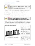
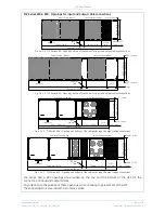
TLE Series 600 - Cabinets positioning and interconnection
Fig. 5.7.1-1 TLE Series 600
–
Cabinets positioning and interconnection
TLE
Series
600
,
in
standard
version,
is
delivered split into two
cabinets,
“Power Section
cabinet”
and
“In/Out
Section
cabinet”
.
Align them together with
the
“Power
Section
cabinet”
on the left side
(cabinet
with
Control
Panel)
.
See
Fig. 5.7.1-1
.
Pay attention, that no
loose cables are trapped
when
pushing
the
cabinets together.
Once finally positioned,
the two cabinets have to
be connected together
with power and control
wiring.
Refer to
Section 5.7.2
and
5.7.3
.
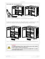
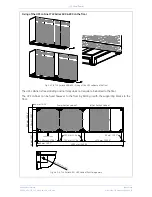
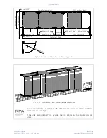
8 Bolt M6x12
Fixing type 2
Fixing type 3a
6 Bolt M6x12
Fixing type 1 (2 pc.)
8 Bolt M6x12
from base
6 Bolt M6x12
Fixing type 3b
In/Out Section cabinet
Power Section cabinet
TLES_600_S1_UPS
connection cabine
ts_GE_01GB
3a 2
3b 1
14.77
"
375
mm
3.
94
"
100
m
m
9.
97
"
253
m
m
35
.55
"
903
m
m
6.
89
"
175
m
m


