

Critical Power
Modifications reserved
Page 132/146
GE_UPS_OPM_TLE_SCE_M60_M80_1GB_V020.docx
User Manual
TLE Series 600 & 800 CE S1
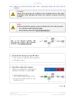
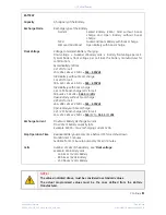
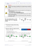
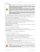
NOTE !
Ensure the
LED 1 (Rectifier)
is lit before carrying out this procedure.
It indicates that the DC-Link has reached 800Vdc (see screen
MEASURES / Rectifier)
!
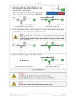
2. Connect the Battery on all Units by closing the
“
External
Battery Protections”.
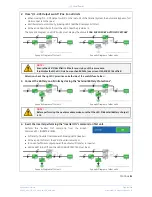
NOTE !
Before performing the next procedure (3) make sure that the
LED 3 (Booster/Battery
charger)
is lit.
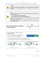
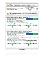
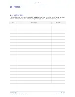
3. Insert the Inverter
performing the “Inverter ON” command
on first unit
.
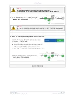
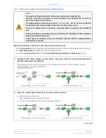
Perform the
“Inverter ON”
command from the screen:
Commands 1 / Inverter /
ON
.
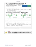
Soft-start
of
Inverter
, indicated with blinking
LED 2 (Inverter)
.
At the end of
Soft-start
the
LED 2 (Inverter)
remains lit.
In case of sufficient output power, the output will transfer to
Inverter.
Synoptic diagram of first unit
Synoptic diagram of other units
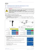
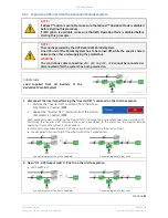
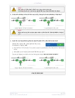
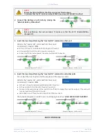
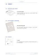
4. Insert the Inverter performing the
“Inverter ON” command
on all other units
.
Do not start the next
Inverter
until the sequence of the previous ends.
Perform the
“Inverter ON”
command from the screen:
Commands 1 / Inverter /
ON
.
Soft-start
of
Inverter
indicated with blinking
LED 2 (Inverter)
.
At the end of Soft-start the
LED 2 (Inverter)
remains lit.
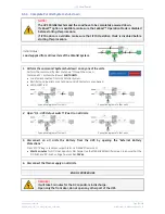
As soon as the output power of the
Inverters
is sufficient to supply the
Load
, the output of the units with
running
Inverter
will transfer to
Inverter
.
LED ALARM
turns Off and the
LED LOAD PROTECTED
must be lit.
The
Synoptic Diagram
, on all UPS units, must display the status
“
LOAD SUPPLIED BY INVERTER
”
.
Synoptic diagram of first unit
Synoptic diagram of other units
END OF PROCEDURE


