


Critical Power
Modifications reserved
Page 30/146
GE_UPS_OPM_TLE_SCE_M60_M80_1GB_V020.docx
User Manual
TLE Series 600 & 800 CE S1
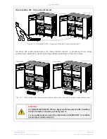
TLE Series 600 & 800 -
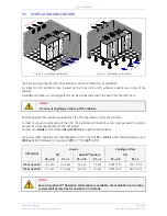
Moving the UPS cabinet
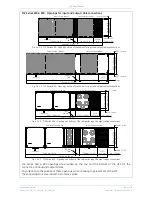
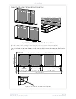
Fig. 5.4.1-2 TLE Series 600 & 800
–
Moving
the UPS cabinet (“Power Section cabinet”)
TLE Series 600 & 800,
positioned in the
“Power Section cabinet”,
is provided with two bases
reinforcement support (A) to avoid any damage during transportation of the UPS cabinet.
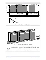
Fig. 5.4.1-3 TLE Series 600 & 800
–
Removing the two bases reinforcement from the
UPS cabinet (“Power Section cabinet”)
WARNING !
It’s MANDATORY REMOVE the two base
s reinforcements (A) after installing
the UPS and before the start-up. See
Fig. 5.4.1-3
.
For any subsequent moving of the UPS cabinet is MANDATORY to re-install
the two bases reinforcement (A).
A
TL
ES_
60
0-
80
0_
S1
_U
PS
m
ovi
ng
_0
1
EP
O
- +
1
2
A
TLE Series 800
“Power Section” cabinet
TLE Series 600
“Power Section” cabinet
EP
O
- +
1
2
A
A
E
PO
E
PO
- +
1
2
A
E
PO
E
PO
- +
1
2
TLE Series 800
TLE Series 600
“Power Section” cabinet
“Power Section” cabinet
A
TL
ES_
600
-8
00
_S1_U
PS
m
oving
_0
2


