Critical Power
Modifications reserved
Page 126/146
GE_UPS_OPM_TLE_SCE_M60_M80_1GB_V020.docx
User Manual
TLE Series 600 & 800 CE S1
8.3.2
Separate a UPS unit from the Redundant Parallel System
NOTE !
If
eBoost™
option is available, make sure that
eBoost™ Operation Mode
is disabled
before starting this procedure.
If
IEMi
option is available, make sure that
IEMi Operation Mode
is disabled before
starting this procedure.
NOTE !
The
Load
is powered by the
UPS Redundant Parallel System
.
One UPS unit of the
Parallel System
has to be turned Off, while the
Load
is shared
between the other units supplying the parallel bus.
WARNING !
The control bus cable connecting
J1A - J2A
and
J1B - J2B
cannot be connected or
disconnected after the system has been powered on.
Initial status
:
Load supplied from all Inverters of the
Redundant Parallel System
.
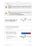
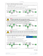
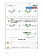
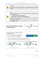
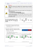
1. Disconnect the Inverter
performing the “Inverter OFF” command
on the Unit to separate
.
1 - Perform the
“Inverter OFF”
command from the screen:
Commands 1 / Inverter /
OFF
.
2 - Repeat the
“Inverter OFF”
command from the screen:
Commands 1 / Inverter /
OFF
.
With
redundant system
, performing the
“Inverter OFF”
command the
Inverter
shuts down and it will stay OFF.
Performing the
“Inverter OFF”
command the
Load
is transferred to the
Mains
and the
Inverter
remains
operating, it means the system is not redundant.
In this case is not possible to switch-OFF one unit without transferring the
Load
on
Mains
.
Load
supplied from
Inverter(s)
of the other Unit(s) of the
Parallel System.
Synoptic diagram of the unit to separate
Synoptic diagram of other units
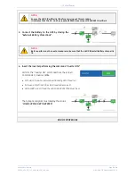
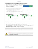
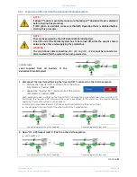
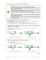
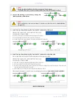
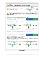
2. Open
“Q1
-
UPS Output switch”
(Pos. O) on the Unit to separate.
LED ALARM
is lit.
Synoptic diagram of the unit to separate
Synoptic diagram of other units
Continue
►


