31
4. Installation
Important!
The following information must be read to install your
PhastSystem instruments correctly.
Unpack the equipment carefully and check the contents of the carton
against the packing list. Save the packing material and the carton in
case PhastSystem must be returned. Check the equipment for any
visible signs of damage that may have occurred during shipment.
Removal of locking screw
Remove the locking screw on the left of the underside of the
development unit. The air pump is mounted on a rubber support and
fixed with this screw during shipment. Save the locking screw in case
you should ever need to ship the unit. (Leaving the screw in place will
make the unit noisier but will not affect the operation.)
Unpacking the electrodes
Carefully remove the plastic packing material from the electrode unit
in the separation compartment of the separation and control unit.
Check that the electrodes are straight.
Voltage selector setting
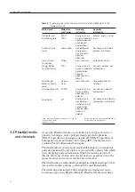
PhastSystem instruments are available in two versions: for 220/240 V
AC, and for 110/120 V AC electricity supplies.
Check that the instruments have the correct voltage and code number
printed on their back panel.
220/240 V
18-1018-24
Separation-Control and Development Units
18-1200-10
Separation Control Unit
110/120 V
18-1018-23
Separation-Control and Developments Units
18-1200-00
Separation Control Unit
4.1 Unpacking
4.2 Cable
connections
4. Installation


