GE Medical Systems
EAGLE 1000
Page 42
Information Technologies
Servicing Instructions 227 468 01 Rev.G
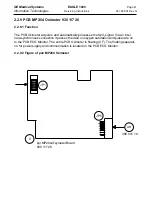
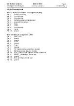
2.2.9.3 Pin assignment
Sensor interface connector pin assignment (JP1)
Pin 1:
Anodes (detector)
Pin 2:
no connection
Pin 3:
no connection
Pin 4:
Cathode (detector shield) shield
Pin 5:
ground (RCAL return)
Pin 6:
RCAL
Pin 7:
-LED
Pin 8:
no connection
Pin 9:
+LED
Pin 10:
ground
Host interface pin assignment (JP5)
Pin 1:
VCC (+5V)
Pin 2:
ground
Pin 3:
ground
Pin 4:
+7.5V
Pin 5:
ground
Pin 6:
-7.5V
Pin 7:
unused
Pin 8:
TX Transmit data (output from module)
Pin 9:
RX Receive data (input to module)
Pin 10:
CTS_ Clear to send (input to module, active low)
Pin 11:
RESET_ (Reset input, active low)
Pin 12:
ground
Pin 13:
ECG sync input, active high
Pin 14:
ground
Summary of Contents for Eagle 1000
Page 1: ...Eagle 1000 Patient Monitor Servicing Instructions 227 468 01 SA e Revision G ...
Page 121: ......
Page 122: ......
Page 123: ......
Page 124: ......
Page 125: ......
Page 130: ......
Page 135: ......
Page 136: ......
Page 138: ......
Page 141: ......
Page 142: ......
Page 143: ......
Page 144: ......
Page 145: ......
Page 146: ......
Page 147: ......

