GE Medical Systems
EAGLE 1000
Page 38
Information Technologies
Servicing Instructions 227 468 01 Rev.G
2.2.8 ECG signal preprocessing
2.2.8.1 Functional description
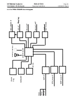
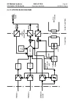
The block diagram ECG/Pace Preprocessing shows the functional setup.
ECG input
In the Eagle 1000 ECG signal acquirement and processing takes place in one of the
remaining functional groups electrically separated from the others on the motherboard.
The functions of this component comprise analog processing of the ECG signals and a
QRS detector to monitor the cardiac rhythm.
All control functions are monitored by a processor, which exchanges data and commands
with the ECG circuit via the optoelectronic coupler.
Before it becomes operative the ECG circuit must be initialized. This is effected by the
processor in accordance with the selected accessories. The processor receives ID signals
called LET1, LET2 and LET3, identifying the nature of the connected accessories and,
hence, determines which ECG leads are available and which connections need to made
to the patient.
For this reason, the lead selector is preset to identify the patient cables used and to test
whether all the electrode leads are connected correctly. Every disconnected (electrode)
lead produces an error signal which is evaluated by the processor so that such electrodes
are not used for ECG monitoring.
ECG signal transfer
If fully operational electrodes are correctly connected to the EAGLE 1000, the ECG signal
is first amplified to 1.1 V per 1 mV as an analog signal, then transferred as a digital signal
via the optoelectronic coupler.
During analog signal amplification signal transfer is interrupted in the event of pacemaker
pulses and the arithmetic mean value is transferred as a baseline in place of the ECG
signal. The digital data are generated 1000 times a second from each of the transferred
amplitude values.
ECGs up to max. ±4.5 mV are digitized completely.
Three-lead patient cables provide only one ECG lead (lead I, II or III) on channel 1, con-
necting a five-lead cable enables EAGLE 100X to provide one lead each on two channels.
The options are leads I, II, III, AVR, AVL, AVF, V.
Summary of Contents for Eagle 1000
Page 1: ...Eagle 1000 Patient Monitor Servicing Instructions 227 468 01 SA e Revision G ...
Page 121: ......
Page 122: ......
Page 123: ......
Page 124: ......
Page 125: ......
Page 130: ......
Page 135: ......
Page 136: ......
Page 138: ......
Page 141: ......
Page 142: ......
Page 143: ......
Page 144: ......
Page 145: ......
Page 146: ......
Page 147: ......

