GE Medical Systems
EAGLE 1000
Page 72
Information Technologies
Servicing Instructions 227 468 01 Rev.G
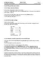
3.2.4 ECG performance check
3.2.4.1 Patient cable identification
Connect the 3-lead patient cable to the monitor.
Press the F1 key
[ECG]
and then press the
[Channel 1]
key. It should only be possible to
select leads I, II and III.
Connect up the 5-lead patient cable and hold down the
[Channel 1]
key.
It should now be possible to select from:
I, II, III, AvR, AvL, AvF and V.
3.2.4.2 ECG Simulator settings
Switch on the simulator.
Connect up 5-lead patient cable with the following correct electrode configuration and
program the appropriate settings:
IEC cable
red
----------> RA
yellow
----------> LA
green
----------> LL
black
----------> RL
white
----------> C/V1
Amplitude
1mV
Heart rate (RATE)
60
3.2.4.3 Analysis of the ECG signal, HR value and QRS beep
Select the various leads for
[Channel 1]
and
[Channel 2]
, all possible leads should be
available.
The ECG waveforms must be noise-free.
The heart rate of 60 bpm +/-2 bpm appears on the display.
In the main menu actuate the F5
[Next Menu]
button, until you reach the menu op
tion
[QRS/Pulse Beep]
. Enable function by pressing the F3 key
[QRS/Pulse Beep]
.
When
[HR Source ECG]
is enabled an acoustic impulse will be triggered after every QRS
complex.
Now disable the acoustic impulse.
Enable the square wave impulse function on the ECG pulse generator. Select Lead II for
[Channel 1] and [Cheannel 2]. The square wave impulse waveform should correspond to
the amplitude of the displayed 1 mV reference pulse (only valid for the above-mentioned
pulse generator).
Summary of Contents for Eagle 1000
Page 1: ...Eagle 1000 Patient Monitor Servicing Instructions 227 468 01 SA e Revision G ...
Page 121: ......
Page 122: ......
Page 123: ......
Page 124: ......
Page 125: ......
Page 130: ......
Page 135: ......
Page 136: ......
Page 138: ......
Page 141: ......
Page 142: ......
Page 143: ......
Page 144: ......
Page 145: ......
Page 146: ......
Page 147: ......

