GE Medical Systems
EAGLE 1000
Page 47
Information Technologies
Servicing Instructions
227 468 01 Rev. G
2.2.11 PCB Press-Temp 388 031 75/PCB Temp 388 032 04
General information
The PCB PRESS-TEMP enables measurement of the two electrically isolated parameters
temperature (one temperature) and invasive blood pressure (two pressures,both isolated
together). These parameters are connected along with the ECG to the processor by me-
ans of a QSPI interface. The signals are isolated by optoelectronic couplers.
The power supply is fed in via one HF transformer each for PRESS and TEMP from a
common oscillator, which also supplies power to the ECG circuit and the SpO
2
module.
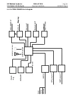
See block diagram Floating system supply and signal flow.
The PCB is equipped with precision components (and an adjustment program in the case
of TEMP) so that a
potentiometer adjustment is not required.
The individual floating measurement circuits are shielded on both sides of the PCB by a
metal cover. For PCBs which do not have an insulating cover over the two floating parts
the PCB is underlayed with a sheet of insulating foil. These insulation precautions are
important for safety reasons!
2.2.11.1 PRESS module
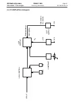
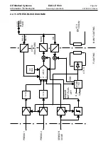
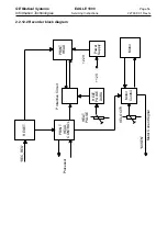
The circuit is described in the block diagram Press block diagram.
Power supply
The floating power supply for PRESS uses an HF transformer connected in parallel with
the other floating transformers. The corresponding oscillator delivers a closed-loop control-
led transformer output voltage, which may vary somewhat depending on the load, from the
unregulated battery voltage. This supplies the amplifier and the connection detector with
±7.5 V.
The ADC and digital circuit are supplied by a voltage controller with a stabilized 5 V, in the
form of an analog and a decoupled digital power supply. When the 5V power supply drops
below 4.75 V an error signal interrupts the chip select to ADC so that no incorrect parame-
ter readings can be transferred.
Probe detection
Each PRESS channel is assigned an ID by means of a resistor coding system which, even
in operation via an adapter, informs the system which channel the probe is connected to or
whether two probes are connected up. This is transmitted to the pro
cessor by a probe ID amplifier as an analog signal via the ADC.
If no probe is connected, this is detected by the probe connection comparator and dis
ables the 5V power supply to save power. The processor is informed of this by the MISO
signal being reset to zero (optoelectronic coupler under continuous current).
Summary of Contents for Eagle 1000
Page 1: ...Eagle 1000 Patient Monitor Servicing Instructions 227 468 01 SA e Revision G ...
Page 121: ......
Page 122: ......
Page 123: ......
Page 124: ......
Page 125: ......
Page 130: ......
Page 135: ......
Page 136: ......
Page 138: ......
Page 141: ......
Page 142: ......
Page 143: ......
Page 144: ......
Page 145: ......
Page 146: ......
Page 147: ......


