background image

100

From 2/4

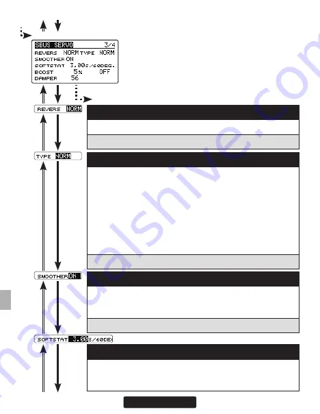
SBUS SERVO screen 3/4

Go to 4/4 from any cursor position

(7) REVERS            

The direction in which the servo rotates can be changed.

Setting:  NORM / REV     

(9) SMOOTHER            

This function changes smoothness of the servo operation relative 
to operation signal changes.  Normally use at Smooth setting. Es-
pecially, select the "OFF" mode when quick operation is necessary.

Setting:  ON / OFF     Initial setting: ON

(10) SOFTSTART            

Restricts operation in the specified direction the instant the power is 
turned on.  By making this setting, only the first operation when the 
power is turned on slowly moves the servo to the specified position.

(8) TYPE            

When "Retractable" is selected and the servo has been continu-
ously stopped for 30 seconds, the dead band expands and unnec-
essary hold current due to external force is eliminated. When a new 
control signal enters, normal operation is resumed. When using the 
servo as a landing gear servo, select "Retractable".  Also adjust the 
servo travel to match the landing gear movement range.  When the 
servo type is OLP mode, the torque and time for OLP can be set on 
SBUS SERVO screen 4/4.  When the load is greater than this set-
ting torque and continues over this setting time, OLP works.

Setting:  NORM / OLP / RETR     

Summary of Contents for CGY755

Page 1: ...ut prior permission The contents of this manual are subject to change without prior notice This manual has been carefully written Please write to Futaba if you feel that any corrections or clarifications should be made Futaba is not responsible for the use of this product INTRODUCTION GPB 1 CGY755 CGY760R GPB 1 Battery Battery Setting Receiving Receiving Setting Receiver Gyro Governor Receiver Gyr...

Page 2: ...ice must accept any interference including interference that may cause undesired operation of the device This equipment complies with IC radia tion exposure limits set forth for an uncontrolled environment This equipment should be installed and operated with minimum distance 20cm between the radiator your body French Cet appareil radio est conforme au CNR 210 d Industrie Canada L utilisation de ce...

Page 3: ...ight Tuning Setting 53 RUD BASIC MENU Rudder Gyro Basic Setting 57 GOV BASIC MENU Governor Basic Setting 61 Governor Speed Setting 68 Governor Operation 68 Recommended Gyro Gain Setting 69 Adjustments During The Test Flight 69 Tips Using The Governor With Electric Models 71 TRANSMITTER Rotor head Gyro GAIN SET UP 72 EXPERT MENU 73 RUD EXPERT MENU Rudder Gyro Expert Setting 74 FLT EXPERT MENU Cycli...

Page 4: ... the e mail address fax or tele phone number listed below Phone 1 256 461 9399 FAX 1 256 461 1059 E Mail service futabaUSA com If you are unable to resolve the issue pack the system in its original container with a note enclosed and a thorough accurate description of the difficulty Include the fol lowing in your note Symptoms including when the problem occurred System Transmitter Receiver Servos a...

Page 5: ...sing angular velocity up to 1 000 deg sec Compatible with 1520 μS Analog 70Hz 1520μS Digital 280Hz and 760μS Digital 560Hz tail rotor servos Feed Forward Option allows the CGY760R CGY755 to consider other control functions during operation This results in more accurate corrections and precise operation Cutting edge control algorithm provides a consistent pirouette rate precise op eration and smoot...

Page 6: ...r section Switch FASSTest 2 4 GHz system and T FHSS 2 4 GHz system using the Gyro Program Box GPB 1 system By S BUS 2 system compatibility it is possible to transmit the battery voltage information of the receiver and the optional sensor information connected to the S BUS 2 port of the receiver Diversity antenna system Other functions Maximum rpm memory Cumulative engine operation timer Integratio...

Page 7: ... Pads x3 Dust Covers x3 X X X Governor Sensor Sensor Mounting Bracket Magnet x2 X Instruction Manual X X X X Decal X X X X CGY755 GPB 1 Governor set CGY755 GPB 1 set CGY755 SET CONTENTS GPB 1 Program Box CGY connection cable Transmitter connection cable Velcro tape for attaching to transmitter X X CGY755 Mounting Pads x3 Receiver connection cable Dust Covers x3 X X X Governor Sensor Sensor Mountin...

Page 8: ...o Program Box When setting up the gyro and the governor connect it to the CGY760R CGY755 and use it Do not install it on the helicopter CGY760R Has receiver function CGY755 No receiver function Magnets 2 Mounting Pads 3 Revolution Sensor ...

Page 9: ... the transmitter to the Gyro Program Box GPB 1 and use the transmitter to transfer the settings of GPB 1 to the CGY760R CGY755 wirelessly Dust Cover 3 REPLACEMENT OPTIONAL ITEMS CGY Connection Cable 350mm It is used to connect the CGY760R CGY755 and the Gyro Program Box GPB 1 Receiver Connection Cable 100mm It is used to connect the CGY755 and the receiver Not included with CGY760R ...

Page 10: ... Prohibited Mandatory WARNING Failure to follow these safety precautions may result in severe injury to yourself and others Read through the entire manual before operating this product USAGE PRECAUTION When using FASSTest 12 CH mode analog servo can not be used for 1 6 CH output for conven tional system The FASSTest system is not compatible with the conventional FASST system CAUTION Do not mount G...

Page 11: ...CONNECTOR INSERTION PRECAUTION WARNING Do not connect the connector by mistake as shown on the right BEFORE EACH FLIGHT WARNING Keep away from conductive materials to avoid short circuits If it does not operate properly during operation test before use or use stop using it Always check the transmitter and receiver battery voltage to ensure they have enough remaining capacity to complete the flight...

Page 12: ...t does so we suggest covering these ares with fuel tubing or similar to prevent damage ABOUT VIBRATION ISOLATION AND WATERPROOFING The CGY760R CGY755 is fixed with a dedicated mounting pad with good condition and the helicopter performs sufficient anti vibration measures so as not to receive strong vibration at the time of flight Also if there is a risk of the gyro getting wet place it in a plasti...

Page 13: ...switch on the transmitter three times between Normal Mode and AVCS Mode Normal AVCS Normal AVCS within one second The servo will center indicating that the new center position has been memorized When operating the gyro in AVCS Mode all compensation and revo lution mixing must be disabled and any tail rotor or swash offsets for flight modes must be disabled Do not drop the CGY760R CGY755 onto a har...

Page 14: ... which the governor is turned off With this setting when the system enters the fail safe state the governor will be turned off and the receiver throttle signal fail safe position preset will be output directly When using the condition hold function on the transmitter always set the throttle servo maximum operating point to less than the point at which the governor is activated If this is not done ...

Page 15: ...gid tail rotor drive system Any modern torque tube or belt drive system should be adequate Do not attempt to fly the CGY using a wire driven tail rotor system Always ensure the drive gears torque tube pulleys belt bearings and shafts are in proper working condition If any of these items are damaged or worn they must be replaced The linkage rod tail rotor bell crank pitch slider and tail rotor grip...

Page 16: ... is rigid Please refer to your model manufacturer s instructions for recommended mounting locations Test fit the gyro sensor ensuring that the sensor is in alignment with the model on the roll and pitch axis The cable from the gyro sensor must exit toward the front or the rear of the model since this is the pitch axis Any misalignment will cause a loss of performance Mounting angle The bottom of t...

Page 17: ...ection axis are aligned with the model However if there is a deviation of equal to or greater than 1 2 degrees performance will degrade In this step please pay special attention to ensure optimum flight performance Refer to the installation example below and select the gyro mounting direction with Gyro Set Dir of the SWH BASIC menu The surface with the CGY mark in the figure is the top LED side of...

Page 18: ...g on the type of mounting plate it is also possible to mount as shown in the figure Depending on the type of mounting plate it is also possible to mount as shown in the figure It is necessary to set the motion direction of each gyro by AGy Dir EGy Dir of SWH BASIC menu page 50 and Gyro Dir of RUD BASIC menu page 58 AIL Aileron Roll axis ELE Elevator Pitch axis RUD Rudder Yaw axis N Normal R Revers...

Page 19: ...nterference could be causing the problem If you feel everything is set up correctly and that the model is vibration free then consider moving the gyro sensor to a new location away from servos ESC and drive motors 3 Vibrations will decrease the performance of all gyro systems Even though the CGY gyro sensor is the most vibration resistant gyro sensor available eliminating vibra tions will always i...

Page 20: ...smitter and receiver close to each other and turn on the receiver with the transmitter in the link mode 3 After powering on the receiver please allow for approximately two seconds for the binding linking to occur 4 The LED indication on the receiver will change from the red blinking light to a solid green This indicates that the linking is successful This usually occurs in approxi mately one secon...

Page 21: ... the power off on once again and or replacing the battery please contact our customer service department 9 P BOX Connect to CGY when making settings When setting is completed remove it 10 Transmitter Connection Cable Connect when using the transmitter to wirelessly transfer settings of GPB 1 to CGY Connecting The CGY RX Receiver LED LED State Solid green Normal operation Solid red No signal recept...

Page 22: ...the throttle servo Connect the ESC w BEC and set the operation mode to Gyro THR mode This diagram shows the various connections between the CGY760R CGY755 and receiver servo or sensors S BUS2 is a system that supports bidirectional communication from a telemetry sensor to a receiver by extending the conventional S BUS Telemetry sensor s etc are connected to S BUS2 connector and used S BUS compatib...

Page 23: ...es not offer enough channels to operate all of the CGY s func tions it is possible to operate the CGY760R CGY755 without the Gov SW Rotor Head Gain channels connected When any of these functions are not used it is necessary to set the channel number to INH within the CGY s S BUS menu Do ing so disables the function and enables the user of the value set in the CGY760R CGY755 menu accordingly When t...

Page 24: ...hole in the direction in which an output is obtained Use epoxy adhesive that cures in 30 minutes or longer Do not use epoxies that contain metal such as JB Weld Sensor Magnet 3 If the cooling fan is unbalanced and vibrates etc balance it by mounting the spare magnet to the opposite side of the cooling fan in the opposite polarity so that it does not output a signal Magnet Cement the magnet to the ...

Page 25: ... gap criteria is approximately 1 to 2mm If a sensor output is not obtained even when the sensor is brought close to the magnet the magnet and sensor center positions may have changed 3 Complete assembly of the sensor by securely tightening the screws that were tem porarily tightened 4 Recheck the sensor output 3 Tighten the sensor stay together with the engine mounting flange Temporary assembly 4 ...

Page 26: ... Countermeasures If the model frame is weak or the engine mount is deformed or not installed prop erly the vibrations applied by the engine will increase Engine vibrations will lead to unstable speed and prevent the governor from providing maximum performance Therefore make sure that the engine is vibration free and that the carburetor provides linear throttle control because the governor can not ...

Page 27: ...o S B2 connectors other than RPM and P BOX Do not connect to RPM and P BOX Connect the battery Opening screen Home screen WRITE screen SBUS SERVO screen CAUTION Be sure to connect and disconnect the CGY760R CGY755 and GPB 1 con nection cable with the power off CAUTION Since the data of CGY or GPB 1 is rewritten always check the operation key Gx P BOX Press and hold the key Press and hold the Esc P...

Page 28: ...creen EXPERT MENU screen GPB 1 setting screen Pressing and keys simultaneously Press the Enter key Press the Enter key Press the Enter key Press and hold the Esc Page key Press and hold the Esc Page key Press and hold the key Press and hold the key Press and hold the Esc Page key ...

Page 29: ...ndition switch When either the DG1 or DG 2 switch is selected the following options are available Function Menu of your transmitter DG1 Assigning DG1 to a switch or flight mode allows the use of two separate values for the condition selectable parameters SWS Rate PIT Rate SWS Ring FLT Styl Cnt AuthAI Cnt AuthEL EXPO HeadHld A HeadHld E StpTune A StpTune E HeadResp BaseGain AI EL CYC Rt GOV Gain L ...

Page 30: ...his screen displays the maximum roll rate and maximum elevator rate recorded during flight Data is reset when the power is turned off If you want to check the maximum rate leave the power on after flight Use the or key to move the cursor to each rate display and press and hold Enter key to reset the display 6 Governor ON OFF Indicates the ON OFF switch status of the governor function When ON is di...

Page 31: ...ress the Enter key to enter the setting mode or key to change the setting con tents When you are done press Enter key to exit setting mode How to set the function with condition C1 The function of each condition is set as follows 1 Use the or key to move the cursor to C and press the Enter key to enter the condition selection mode Use the or key to select the condi tion number C and press the Ente...

Page 32: ...O screen RECEIVER screen GYRO UPDATE screen Press the or key Press the Enter key Press the Enter key to display each menu screen and when the cursor is on the title of each menu screen press the Enter key to return to the GPB 1 screen Press and hold the Esc Page key Press and hold the Esc Page key Pressing and keys simultaneously ...

Page 33: ...GHTNESS with the or key and press the Enter key to enter the setting mode Adjust the brightness with the and keys When you finish adjusting press Enter key to exit setting mode Setting ranges OFF Backlight off 0 20 Initial value 10 3 OFF TIMER Adjust the time until the backlight turns off after the last key operation Move the cursor to OFF TIMER with the or key and press the Enter key to enter the...

Page 34: ... with the or key and press the Enter key to enter the setting mode Select the ON or OFF of key operation sound with the or key When you finish setting press Enter key to exit setting mode Setting ON OFF Initial setting ON 1 LANGUAGE Set the display language of GPB 1 Move the cursor to LANGUAGE with the or key and press the Enter key to enter the setting mode Select the display language with the or...

Page 35: ...e same way as in Receiver System set ACT INH of Internal Rx by pressing the Enter key for about 1 second When Internal Rx setting is INH 1 communication mode is not displayed Setting ACT INH With INH setting the receiv er system will not display RECEIVER screen Note To change the Receiver System type first power off the transmitter and receiver and re power the CGY760R CGY755 while the transmitter...

Page 36: ... our website or your local distributor s website 2 Preparation for update 1 Connect the CGY GPB 1 CIU 2 or CIU 3 to the PC with ref erence to the above connection diagram To the open available slot of CGY GPB 1 CGY A PC that can connect to the Internet and has CIU 2 or CIU 3 driver software installed Double extension cable When there is no connector to connect power to CGY Switch Switch connector ...

Page 37: ...3 or HIGH SPEED CIU3 and press the Enter key The READY indication will appear on screen when the update is available If the update is not performed normally FAILED will be displayed In If the up date has failed please start the process once again from the beginning Should it fail once more it is likely that the update file has been corrupted when downloaded previously Please download this file and...

Page 38: ...E screen SWH BASIC screen RUD BASIC screen GOV BASIC screen SBUS BASIC screen Press the or key Press the Enter key Press the Enter key to display each menu screen and when the cursor is on the title of each menu screen press the Enter key to return to the BASIC MENU screen Press and hold the Esc Page key Press and hold the Esc Page key Press and hold the key ...

Page 39: ...on assignments To change the channel CGY and GPB 1 must be connected From 3 3 Go to 2 3 from any cursor position From the RESET of SBUS BASIC screen 3 3 1 S BUS connection AIL Aileron channel Move the cursor to AIL CH by pressing the or key and press the Enter key to enter the setting mode Use the or key to set the aileron channel of the transmitter When you are done press Enter key to finish Foll...

Page 40: ...ition change channel of the transmitter In this example DG1 is the conditional change channel SBUS BASIC screen 2 3 As with the flight condition function of the transmitter it is possible to utilize pre determined settings each activated by a switch or switches on the transmitter By setting the condition switch on the channel with the AFR function of the transmitter and setting the point for each ...

Page 41: ...r key for about 1 second to to set the channels for the programming via trainer from the transmitter CAUTION Be sure to check the operation for all conditions 1 to 5 before flying The setting of Via transmitter CH is possible only when the transmitter and the CGY are pow ered off and the CGY is turned on Be sure to connect and disconnect the CGY and GPB 1 connection cable with the power off 12 S B...

Page 42: ... be operated with fastest DG 285 Hz mode but some of other brands of servos do not support DG 285 Hz mode In this case select the proper servo driving frequency per the manufacturer s speci fications Move the cursor to Servo Type by pressing the or key and press the Enter key to enter the setting mode Then select the servo type with the or key When EXECUTE Enter 1 sec is displayed press the Enter ...

Page 43: ...rse Normal 3 Set the trainer function as follows according to the transmitter s instruction manual Always ON Teacher Student Teacher Channel mode 16CH Mode for individual channels being used for gyro programming Normal Rate 100 Point In 12 ch FASSTest mode only the first 12 channels can be used for wireless trainer In 18 ch FASSTest it is possible to use 18chs After connecting the GPB 1 to the tra...

Page 44: ...is set up and handled in the CGY and the transmitter functions should not be used Before starting model set up be sure that all dual rates pitch curve and endpoint values are set to 100 100 AIL Aileron servo ELE Elevator servo PIT Collective pitch servo ELE2 Second elevator servo WARNING Do not connect the servo to the gyros until you select the servo type in the SWH BASIC menu If the servo type i...

Page 45: ...e The pro gram will also exit the setting mode accordingly L SCALE Initial parameter mode corresponding to a large machine with a total length of 2 5m or more 2 Gyro Set Dir Mounting direction Set the roll axis pitch axis yaw axis according to the mounting direction of CGY Set mounting direction with reference to page 18 19 Move the cur sor to Gyro Set Dir by pressing the or key and press the Ente...

Page 46: ...servo type parameter within the CGY must match the type of servo you are using Incorrect setting may damage the CGY or the servo Incorrect setting may also result in a loss of control during flight 4 SWASH Type Swash change to plate type Select the swash plate type Move the cursor to SWASH Type by press ing the or key and press the Enter key to enter the setting mode Then select the swash plate ty...

Page 47: ... combination number aileron elevator pitch and 2nd elevator servo parameters are automatically set Note Occasionally the aileron or elevator function directions are re versed even though collective pitch direction is correct In this case use the SWS Dir parameter on the following screen 3 5 to fix this later From 1 5 H1 or H3 SWH BASIC screen 2 5 H4 Go to 3 5 from any cursor position ELE2 is displ...

Page 48: ... selects the aileron elevator and collective pitch direction Reverse the direction when the stick move ment and swash movement are opposite Each time you press the or key the polarity switches 8 SWS Rate Rate adjustment The Swash Rate settings are used to set a known base cyclic throw for the gyro to calculate the compensations and gain scale This value does not represent the total cyclic throw bu...

Page 49: ...ir Aileron roll Gyro direction EGy Dir Elevator pitch Gyro direction This parameter controls which direction the CGY roll pitch axis will compensate when the helicopter rolls pitches Pick the helicopter up and roll the helicopter to the right The CGY should compensate by adding left cyclic to the swash plate Pick the helicopter up and rotate the nose of the helicopter downward The CGY should compe...

Page 50: ...by pressing the or key and press the Enter key to enter the setting mode When EXECUTE En ter 1sec is displayed move the aileron stick to the full right direction Pressing the Enter key for about 1 second will memorize the aileron s direction of motion Be sure to set this aileron motion direction and elevator motion direction so that F F mixing Ele Comp and Rud F F menu works effectively Also pleas...

Page 51: ... the cursor to Pit Zero by pressing the or key Press the Enter key to enter the setting mode EXECUTE Enter 1 sec is displayed Move the collective pitch stick to 0 degree pitch and pressing the Enter key for about 1second The zero pitch signal will be saved to the CGY 16 Pit Low Pitch low memorizing This parameter saves the full negative collective pitch point into the CGY Move the cursor to Pit Lo...

Page 52: ...n and can be adjusted manually on the gyro instead of via the transmitter Setting ranges 0 150 Initial value 100 2 CYC Rt Cyclic rate setting Cyclic rate sets the maximum Cyclic rate sets the maximum roll and flip rate d s as limited by the model s ability to reach that set rate Flip and roll rates are set together with this single parameter The cy clic rate is set by using the or key Setting rang...

Page 53: ...he suggested range for most helicopters Setting ranges 0 100 Initial value Cnt AuthAIL 40 4 Cnt AuthELE Control Authority Elevator Elevator Control Authority changes the rate at which the gyro will try to achieve the set CYC Rt A higher value will create a quicker ac celerated reaction to a stick input to reach and stabilize at the CYC Rt value a lower value will reach the desired CYC Rt slower an...

Page 54: ...reaction to the stick leaving the pilot with the impression that the model is locked into in a position after an input It will also tend to have a more calculated feeling when making inputs Lowering the value will make the model feel more fluid and easy to rotate with the stick input The model will feel a little more lively during faster cy clic movements and direction changes Set by using the or ...

Page 55: ...o rise or fall with collective input increasing ELE Comp will reduce this behavior Setting ranges 0 100 Initial value 0 8 HP Auth High pitch authority When a rotor blades angle of attack is increased the rotor blade be comes less reactive in turn the helicopter might not feel as reactive at high pitch angles If you want to increase the reaction of the cyclic during loaded and high pitch maneuvers ...

Page 56: ... the rudder channel and sensitivity setting channel to 100 5 Temporarily set the D R function of the rudder channel to 75 both left and right 6 We recommend that you temporarily set the EXP function of the rudder channel to about 30 mild side 30 need to clarify what is meant by mild side WARNING Do not connect the tail rotor servo to the gyro until the servo type has been selected Operating the se...

Page 57: ...ng Incorrect settings may damage the CGY or the servo An in correct setting may also result in a loss of control during flight From 2 2 From the Work Mode of RUD BASIC screen 2 2 Go to 2 2 from any cursor position 2 Gyro Dir Gyro direction This parameter controls which direction the CGY yaw axis will com pensate when the helicopter rotates Hold the tail rotor linkage over the linkage ball on the s...

Page 58: ...o arm length to set the mechanical endpoints After that has been completed use the servo limit parameter to make small adjustments that could not be made mechanically Values between 90 and 110 are considered optimal Hold the cursor to Srv Limit by pressing the or key Gradually move the rudder stick to the left or right by the maximum amount the cursor moves Enter the setting mode by pressing the E...

Page 59: ...mal Rate Mode and when AVCS is selected it will always operate in AVCS Mode Use the or key to select the desired working mode Setting CMT Normal AVCS Initial setting CMT 5 GY Gain Gyro base gain setting This parameter sets the base gain of the gyro This can be used to ad just the gain if your actual transmitter gain does not match the gain on the CGY correctly Use the or key to setting the gain Se...

Page 60: ...vernor operation mode of CGY The initial setting is ACT active where as the designation implies the governor is active If you do not want to use governor select INH Inhibit Setting ACT Active INH Inhibit Initial setting ACT 2 Gear Ratio Input the main rotor gear ratio by pushing the or key to select the desired working mode Setting ranges 1 00 50 00t Initial value 8 00t Notes If the gear ratio is ...

Page 61: ...ervo type Digital servos offer the best response Move the cursor to Servo Type by pressing the or key and press the Enter key to enter the setting mode Select the servo type with the or key Pressing the Enter key exits the setting mode Setting Analog DG 1520 Initial setting Analog WARNING The servo type parameter within the CGY must match the type of servo you are using Incorrect settings may dama...

Page 62: ... point This stick switch function is always enabled when the next ON OFF sw is INH or the Governor ON OFF switch is not set by S BUS setting When governor is turned on and off by transmitter throttle stick The data is set so that the governor can be turned on and off with the transmitter throttle stick position The following describes this operation Throttle stick over set point and more than 60 o...

Page 63: ...rnor on or off via a switch on the transmitter Pressing the or key activates the function Choose INH if you do not want to use it Governor can be turned on and off by a switch 8 BAT F S Battery fail safe When the receiver battery voltage becomes equal to or less than BFS Volt set in the GOV EXPERT menu the battery fail safe function is ac tivated the governor function is turned OFF and the throttl...

Page 64: ...setting and repeat this procedure once again GOV BASIC screen 4 6 From 3 6 Go to 5 6 from any cursor position 10 Limit Test Check the set limit point Check the set limit point Use the or key to move the cursor to LIMIT Test Idle and press the Enter key to move the servo to the idle point END will be displayed on screen Similarly on the high side use the or key to select the cursor LIMIT Test HIGH ...

Page 65: ...oo high the RPM itself will fluctuate and surge during flight Setting ranges 1 100 Initial value Nitro 40 1 1Magn 60 HPoleEP 30 LPoleEP 10 13 L Lmt L rpm H rpm Low limit RPM Low RPM Limit sets the minimum amount of throttle that the governor will command during an over speed situation Too low of value the engine could shut off or not recover power quickly enough during the next collective movement...

Page 66: ...rnor operation Also when using the backplate sensor the signal level of the backplate sensor varies depending on the rotation speed 3 000 rpm or more is the de tectable rotation speed Go to 1 6 from any cursor position Go to 6 6 from any cursor position By the telemetry function the number of revolutions read by the governor sensor can be displayed on the monitor of the transmitter In order to be ...

Page 67: ...o your transmitter s manual Using by 3 position switch Set the RPM at each switch position in the 5 RPM setting menu within the Gov ernor Basic Setting section earlier in this manual Governor operation The CGY operates from 700 to 4000 rpm main rotor speed However the engine must be running at the set speed The CGY turns off the governor when the engine is starting or idling Condition of the gover...

Page 68: ...r the gyro tape is torn or peeled Turn on the transmitter receiver and initialize the gyroscope Check whether the servo type setting matches the servo being used Rudder Swash Check that the servo horn is neutral and perpendicular to the push rod Rudder Swash Confirm that the maximum servo movements are not physically bound through out the range of motion Rudder and swash Check that the gyro is ope...

Page 69: ...d properly by verifying that the gyros are compensating as the helicopter is moved It is recommended to use a power switch on the power supply line to avoid this possibility Rudder Gyro Trim Flight The tail rotor rudder AFR or D R function within the transmitter is used to adjust the pirouette rate of the helicopter to suit your requirements Do NOT use ATV or rudder channel travel adjustment for t...

Page 70: ...rate your ESC Make sure you calibrate the governor speed ranges in the transmitter s governor menu and set the high and low limits for throttle in the Governor Basic menu If a tail kick or jerk is observed when switching from one idle up head speed to another INCREASE the Revolution Up and Down delays Revo Up Dlyo Revo Dn Dly GOV EXPERT Menu Increase 2 5 at a time until the tail kick is suppressed...

Page 71: ...should list all three gain channels Adjust ments can be made from within this function The gyro function can usually be as signed to various switches or conditions to offer greater adjustability Please refer to your transmitter s instruction manual for further details Setting the CGY gains by using endpoints or manual adjustments 1 If your transmitter does not support the remote gain adjustment it...

Page 72: ...n FLT EXPERT screen RUD EXPERT screen GOV EXPERT screen Press the or key Press the Enter key Press the Enter key to display each menu screen and when the cursor is on the title of each menu screen press the Enter key to return to the EXPERT MENU screen Press and hold the Esc Page key Press and hold the Esc Page key Press and hold the key ...

Page 73: ... neutral position with the or key When you finish adjusting press Enter key to exit setting mode Setting ranges 240 0 240 Initial value 0 2 EXP AVCS EXP NORM Rudder exponential This parameter sets the feel of the tail rotor control around center When set to 0 the control curve is linear Using a value the tail rotor will be more sensitive around neutral conversely using a value will soften the feel...

Page 74: ...ss the Enter key to exit the setting mode Follow these same procedures to adjust the tail rotor feel in the opposite direction Setting ranges 0 20n Initial value 15n 4 CNT DlOut Control delay out This parameter sets the delay when the stick is returned back to the neutral position This parameter is useful to tune how aggressively the tail rotor stops following a pirouette The higher the value the ...

Page 75: ...ounteract sudden increases in torque from the motor during fast collective pitch changes If you notice a tail kick using right rudder on Clockwise rotor disk left rudder on CCW F F mixing can be tuned to reduce the tail kick The mixing amount can be individually set for high pitch side U and low pitch D side with zero pitch as the center Setting ranges 100 0 100 Initial value 0 RUD EXPERT screen 3...

Page 76: ...ting late will increase the gyro sensitivity and improve the control performance Also if the response setting is delayed the power con sumption of the servo will be reduced However if the response setting is too late the operation cannot keep up with high speed operation of the helicopter Setting ranges 1 5 Initial value 1 RUD EXPERT screen 5 5 Go to 1 5 from any cursor position From 4 5 Go to the...

Page 77: ...o exit the setting mode Cond Cond Cond 1 HeadHld A HeadHld E Head hold aileron elevator This features is used to adjust the heading hold aspect of the gyro con trol If the helicopter is not holding angle or cyclic control rates increas ing the heading hold gain will improve holding the helicopter at a certain angle and improve the cyclic rate consistency If this is set too high you could see an os...

Page 78: ...he heli copter is capable of reacting In a standard helicopter a Head Response of 1 should always be used but on some scale applications or uniquely designed rotor heads increasing head response might be needed to cure over correction of the gyro Setting ranges 1 10 Initial value 1 5 DeadBand Dead band Transmitter control dead band If you are noticing inconsistent swash plate drift or poor initial...

Page 79: ...y pressing the or key and press the Enter key to enter the reset mode With EXECUTE Enter 1 sec displayed press and hold the Enter key for about 1 second to initialize FLT Tun setting If you do not wish to reset press Enter key or Esc Page key to exit the reset mode Go to the menu title of FLT EXPERT screen 1 2 ...

Page 80: ...ID to HIGH and MID to LOW collective pitch check that the swash plate is traveling flat throughout the entire range Using the or key to level the swash plate on the aileron axis to the middle point by raising or lowing the aileron servo Setting ranges 30 150 Initial value 100 2 PIT ELE collective pitch elevator mixing rate Going from MID to HIGH and MID to LOW collective pitch check that the swash...

Page 81: ...adjusted individually for both full high and low collective positions Note This setting is only available if the H4 xx swash mode has been selected Setting ranges 30 150 Initial value 100 5 AIL ELE aileron elevator mixing rate This parameter adjusts the aileron to elevator mixing rate The rate can be adjusted for left and right directions individually Note This setting is only available if the H4 ...

Page 82: ...evator aileron mixing rate While moving the elevator back and forth at middle collective check to make sure the aileron axis is staying level Use the or key to raise or lower to level the swash plate so that it remains level during full forward and back elevator input Note This setting can not be used when H4 00 swash mode is selected Setting ranges 30 150 Initial value H3 120 50 except H3 120 100...

Page 83: ...nputs If the swash plate is rising or falling use the or key to maintain the swash plate position the same as that noted in the centered aileron inputs Note check all four directions high right high left low right low left Setting ranges 0 100 Initial value 0 11 AIL Dir Compensation direction of the aileron If the above Data correction from 0 100 is NOT in the correct com pensation direction chang...

Page 84: ... inputs If the swash plate is rising or falling use the or key to maintain the swash plate position the same as it is in the middle during elevator inputs Note check all four directions high back high forward low back low forward Setting ranges 0 100 Initial value 0 13 ELE Dir Compensation direction of the elevator If the above Data correction from 0 100 is NOT in the correct com pensation directi...

Page 85: ...except H3 120 0 15 SWASH Rot Swash rotation Using the or key electronically add rotor head phasing to the swash plate controls If possible it is recommended to use mechanical phasing adjustment but if the rotor head does not allow this and you feel that the model is NOT flying axially on each control input this parameter can be used to adjust the pure reaction of each axis in flight Typi cally adv...

Page 86: ...aults Move the cursor to RESET by pressing the or key Press the Enter key to enter the reset mode When EXECUTE Enter 1 sec is dis played press and hold the Enter key for about 1 second to initialize SWH DETAIL setting If you do not wish to reset press either the Enter key or Esc Page key to exit reset mode Go to the menu title of SWH DETAIL screen 1 7 ...

Page 87: ...nt RPM throughout flight Rev Lmt Limiter Mode Throttle control follows the throttle curves to advance the throttle position during flight but controls the RPM during throttle reduction by not letting the RPM overspeed past the set RPM When the Rev Lmt mode is selected the menu 5 THR Mode should be set to Tx Curve mode Setting GOVERNOR Rev Lmt Initial setting GOVERNOR 2 Revo Disp Governor working m...

Page 88: ... to more rapidly correct for changes in power demands of the model resulting from yaw input Set the mode to match the gyro installation direction Select from CW TOP CW BOTM CCW TOP CCW BOTM by pressing the or key Note if the user has selected the governor only mode this parameter is inhibited Revolution fluctuation in the case of pirouettes The governor detects the rpm via the revolution sensor mo...

Page 89: ...M change rate Setting ranges 2 40Frm Initial value 10Frm 8 Start Dly Start delay How quickly the RPM stabilizes to the set RPM from when the GOV is turned ON A higher value slows down the spool up rate a lower value speeds up the spool up rate Setting ranges 2 20Frm Initial value 5Frm 9 Gov On Revo Governor ON revolution setting This parameter tells the governor at what percentage of the set rpm i...

Page 90: ...tting This value is set to assign the lowest possible governing RPM If the RPM is below or can not reach this RPM the governor will not engage Select between either 1 000 rpm or 700 rpm It corresponds also to a helicopter with a rotor speed of 1 000rpm or less such as a large gas machine Setting 700 1 000rpm Initial setting 1000rpm 12 RESET Governor expert data reset This resets the GOV EXPERT set...

Page 91: ...nd CGY are the same Press and hold the Esc Page key Press and hold the Esc Page key Opening screen WARNING After writing if the setting is INH the internal receiver is operating without turning off the power supply once If the receiver is connected while it is op erating the helicopter crashes with inoperable state CAUTION If you press Ent start from the opening screen and display the home screen ...

Page 92: ...ch GPB 1 Battery CAUTION Be sure to connect each servo and set it If multiple servos are connected at the same time the servo may be damaged Be sure to turn off the power when replacing the servo Servo may be damaged if servo is replaced while power is on Please match the voltage of the battery to be used with the specifications of the servo to be connected Servo will be damaged if voltage higher ...

Page 93: ...Enter 1 sec is displayed press and hold the Enter key for about 1 second To cancel select press Enter key or Esc Page key to exit the recall mode COMPLETED is displayed on the screen and the ser vo s ID cord and currently set channel are read If FAILED is displayed on the with the servo is not be ing performed normally Please turn off the power of the GPB 1 connect the servo again turn the power o...

Page 94: ...gain 3 INIT Write the factory set servo setting data to the con nect ed servo Move the cursor to INIT by pressing the or key Press the Enter key to enter the writung mode When EXECUTE Enter 1 sec is displayed press and hold the Enter key for about 1 second To cancel select press Enter key or Esc Page key to exit the recall mode The setting of the channel setting and servo type 760us 1520us is not ...

Page 95: ...sible with the servo type function Display of servo type when reading When RECALL is executed the servo type name is displayed on the left side of the screen and the current 760 or 1520 type is displayed below it The S BUS servo not supporting servo type change displays Unsupported A new S BUS servo example HPS H700 that can set both parameters for swash SWH 760 and Rudder RUD 760 is loaded first ...

Page 96: ...2 If the CH setting is DG1 or DG2 the servo type can not be changed Before changing to Servo type you need to set it to CH1 to 16 with CH setting and execute WRITE CAUTION The servo of 760 μS is not connected to ordinary CH SBUS SBUS 2 connector such as receiver not compatible The servo may be damaged Do not set 760μS servo parameters with transmitter unsupported to 760μS and PC S LINK software Be...

Page 97: ...e some functions which cannot be used If a function cannot be used the display screen will change Go to 2 4 from any cursor position 1 CH Channel of the S BUS system assigned to the servo Always assign a channel before use Note Since servo with servo type set to 760μS DG 760 can not be used as S BUS system CH setting can not be selected 2 Servo Type This function changes 760μS type and 1520μS type...

Page 98: ...multiple servos can be matched without being affected by motor fluctua tions This is effective for load torques below the maximum torque However note that the maximum speed will not exceed what the servo is capable of even if the servo s operating voltage is increased 5 DEADBAND The dead band angle at stopping can be specified Relationship between dead band set value and servo operation Small Valu...

Page 99: ...ting only the first operation when the power is turned on slowly moves the servo to the specified position 8 TYPE When Retractable is selected and the servo has been continu ously stopped for 30 seconds the dead band expands and unnec essary hold current due to external force is eliminated When a new control signal enters normal operation is resumed When using the servo as a landing gear servo sel...

Page 100: ...servo is stopped can be set When smaller than the standard value the characteristic becomes an over shoot characteristic If the value is larger than the standard value the brake is applied before the stop position Especially when a large load is applied overshoot etc are suppressed by in ertia and hunting may occur depending on the conditions If hunting phenom ena which cause the servo to oscillat...

Page 101: ...e becomes weaker Large Value Setting Servo holding force becomes stronger Note When this parameter is large the current consumption increases 14 BUZZER When a servo is powered up without a transmitter signal a buzzer sounds When transmitter signal is lost a buzzer sounds until the servo regains the signal This is not unusual The transmitter has been turned OFF ahead of a servo power supply The buz...

Page 102: ...ou are setting 16 TIME This is the time for working OLP Set the time when OLP Over Protection functions Displayed only when the type is OLP setting Setting 0 2 0 5 1 2 3sec 4 5 6 7 8 9 10 15 20 25 30sec Initial setting 5sec Note If the setting of OLP torque and time is decreased it is easier to work OLP Then please be careful not to work OLP at usual operation The changeable S BUS servo of 760μS a...

Page 103: ... Transmitter Connection Cable CGY Connection Cable Trainer jack of the transmitter S I F of T32MZ CAUTION Be sure to check the operation for all conditions 1 to 5 before flying Be sure to connect and disconnect the transmitter and GPB 1 connection cable with the power off Futaba transmitters other than T32MZ have only one connection T32MZ need two connections No need other than T32MZ ...

Page 104: ...GOV BASIC GOV Gain Governor gain page 66 L Lmt L rpm Low limit hovering RPM page 66 L Lmt H rpm Low limit idling RPM page 66 FLT EXPERT HeadHld A Head hold aileron page 78 StopTune A Stop tune aileron page 78 HeadResp Head Response page 79 HeadHld E Head hold elevator page 78 StopTune E Stop tune elevator page 79 RUD EXPERT EXP AVCS Rudder exponential AVCS page 74 EXP NORM Rudder exponential NORMA...

Page 105: ...GY760R CGY755 GY701 GY520 or DSC cable for update Receiver battery 1 Download the CGY760R CGY755 update file from our website or your local distribtor s website 2 Extract the zip file on your computer A PC that can connect to the Internet and has CIU 2 or CIU 3 driver software installed Double extension cable Switch Battery CIU 2 or CIU 3 To PC USB port CGY connection cable 3 Connect as shown in t...

Page 106: ...lick PC side 4 Start an executable file by a PC GPB 1 side 5 When using the CIU 3 hold down the Enter and Esc Page keys of the GPB 1 and turn on the power Release the Enter and the Esc Page keys when the backlight of the screen lights up When using the CIU 2 hold down the and keys of the GPB 1 and turn on the power Release the and keys when the backlight of the screen lights up ...

Page 107: ...about 50seconds 5minutes Click WRITE OK WRITE PC side GPB 1 side When using the CIU 2 When using the CIU 3 Don t turn on the power CAUTION Do not turn off the power or re move the battery while updating GPB 1 may be damaged ...

Page 108: ...d message SUCCESS appears 7 Check the GPB 1 program version on the Information screen 8 Be sure to check each setting and check the operation before using If the cable disconnects or a contact failure occurs during the update the update stops halfway In that case please try updating again from the beginning If the GPB 1 fails to update or does not start please have it serviced ...

Page 109: ...e mounting plate accordingly Screw size for attachment The effective length of the screw hole of the CGY main unit is 7mm Use the M3 screw whose length is less than the plate thickness plus 7mm Mounting Attach the CGY to the mounting plate using M3 screws from the bottom of the plate as shown in the example Ensure that the screws are no longer than the plate thickness plus 7mm Notes Ensure that th...

Page 110: ...Operating Temperature 14 F to 113 F 10 C to 45 C Size CGY760R 1 055in 26 8mm W 1 476in 37 5mm L 0 63in 16mm H Weight CGY760R 0 713oz 20 2g CGY755 Control System Digital advanced control Angular Velocity Range 1 000 Degrees Per Second Gyro Sensor Micro Electromechanical Systems MEMS Gyro Hall effect sensor Governor Resolution 0 1Hz 6rpm Engine RPM RPM Accuracy 1 Head Speed Range 700 4 000rpm Select...

Page 111: ... Drain 62mA Operating Temperature 14 F to 113 F 10 C to 45 C Display 128 x 64 dot graphics Size 2 126in 54mm W 3 543in 90mm L 0 6102in 15 5mm H Weight RPM sensor 1 88oz 53 3g The operating voltage shown only applies to the CGY760R CGY755 and GPB 1 Always verify that your receiver servos tail rotor servo switch and any other electronic components used in your installation are capable of oper ating ...

Page 112: ......

Reviews: