background image

33

Stuck log procedure

If a log does not split completely and becomes stuck on the wedge (18), never attempt to 

remove it by modifying the splitter or adding attachments to the splitter. Move the control 

lever (1) to the Reverse position and allow the cylinder to retract until the stuck log contacts 

the wedge cover guard (17). Continue to retract the cylinder until the log is dislodged from 

the wedge (18).

OPERATION (cont.)

IMPORTANT!

 Do not use the unit if the wedge cover guard (17) is bent or 

damaged. Bent or damaged cover guard must be repaired or replaced before use.

WARNING!

 Stand in safe working zone, so feet are not in the path of falling logs.

WARNING!

 Do not hold wood in position to be split, with any part of your body 

once the control lever is moved into the forward or reverse position.

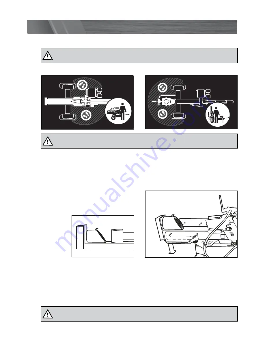
¥  The splitting operation of the machine is designed to be activated by one person only.

Log placement (fig. 66 & 67)

¥  Load a log onto the beam and against the end plate (15). Log should be cut as square as 

possible, to fit properly on the log splitter and against the end plate.

¥  If logs have an uneven end, it is best that 

the uneven end is placed towards the 

wedge (18), with the log edge facing down.

Horizontal lock latch

Horizontal lock latch

HORIZONTAL OPERATING ZONE 


VERTICAL OPERATING ZONE

Fig. 66

Fig. 67

Summary of Contents for FBLS-22T

Page 1: ...ctions before use Failure to follow the warnings and instructions may result in electric shock fire and or serious injury Save these instructions for future reference 1217 22 TONNE SPLITTING FORCE 6 5...

Page 2: ...tres Oil capacity 470 590ml Displacement 208cc Speed 3 600rpm max Log splitter specifications Splitting force 22 Tonne Log length maximum 600mm Table size 610 x 310mm Cylinder operating speed 60mm s a...

Page 3: ...bar 20 Manual tube 21 Wheel guard right side 22 Log cradle right side 23 Log cradle engine side 24 Axle 25 Muffler 26 Horizontal beam lock 27 Assembly hardware 27 18 x 135 x 1 1 R Clip x 1 M10 x 35 x...

Page 4: ...INSTRUCTIONS Page 05 ASSEMBLY Page 11 FEATURES AND CONTROLS Page 24 SETUP AND PREPARATION Page 27 OPERATION Page 31 TRANSPORTING Page 34 MAINTENANCE Page 36 STORAGE Page 38 TROUBLESHOOTING Page 39 DES...

Page 5: ...r petrol log splitter It has been designed to split wood logs for use as firewood for a wood heater or fireplace The log splitter will only split logs lengthwise with the grain and is capable of split...

Page 6: ...t children to operate this machine at any time Keep children pets and other people not using the unit away from the work area Be alert and shut off unit if anyone enters work area Keep children under...

Page 7: ...plitter in dry areas as a precautionary measure Fuel safety Fuel is highly flammable and its vapours can explode if ignited Take precautions when using to reduce the chance of serious personal injury...

Page 8: ...esult in serious injury or death Be sure to stop the engine and relieve hydraulic pressure before doing any work on hydraulic parts Keep body and hands away from pin holes or nozzles that expel hydrau...

Page 9: ...t muddy or slippery ground Only operate your log splitter on level ground IMPORTANT Operating on a slope could cause the log splitter to roll over or logs to fall off the equipment which could result...

Page 10: ...res for excessive wear cuts or damage Check for proper tire inflation Add air as required Do not over inflate tires Serious injury can result if tires explode Check before towing to make sure the log...

Page 11: ...e over 16kg two person lift is required to avoid injury Beam Assembly Engine Assembly It is required that a minimum of two people assemble the log splitter 18 x 135 x 1 R Clip x 1 M10 x 35 x 6 M12 x 3...

Page 12: ...shipped hanging from the valve on the handle link Remove the pin and split pin from the control lever 1 move the control lever 1 to the vertical Neutral position fig 4 2 Reinstall the pin and split p...

Page 13: ...s and align post mount with cutouts in frame fig 6 M10 x 35 x 6 M12 x 35 x 8 6 x 40 x 2 M8 x 20 x 2 M8 x 20 x 8 M10 x 25 x 4 Roll Pin M10 x 25 x 2 Hydraulic Cylinder Engine Assembly Post Fig 6 4 Insta...

Page 14: ...20 x 2 M12 x 30 x 4 Axle Nut Washer x 1 Split Pin 4 x 50 x 1 x 1 M8 x 20 x 8 M10 x 25 x 4 Wheel Cap Roll Pin U shaped Lock Pin Washer Sping M10 x 25 x 2 Wheel assembly First wheel Tools required not s...

Page 15: ...it Pin Bearing Anti dust Washer Axle Nut Wheel Cap Washer Bearing Anti dust Washer Sleeve Fig 10 Fig 11 6 Loosen the axle nut until it is loose enough to turn the wheel 11 with your fingers then retig...

Page 16: ...wheel axle is against the wooden block fig 13 4 Hold the hydraulic cylinder handle 3 and slowly stand the beam assembly 16 on the end plate 15 in the vertical position fig 14 M8 x 45 Wooden Block Upp...

Page 17: ...e lower bracket and upper bracket Insert each bolt with washer from the underside Secure in place with a washer and nut fig 16 Note Only tighten after all 4 bolts are assembled in place Wheel assembly...

Page 18: ...e to the engine Secure in place with bolt flat washers and spring washers fig 18 M10 x 35 x 6 M12 x 35 x 8 M12 x 80 x 2 x 1 x 1 6 x 40 x 2 M8 x 20 x 2 M8 x 20 x 8 M10 x 25 x 4 Roll Pin U shaped Lock P...

Page 19: ...r hole on the beam bracket Insert the long end of the U shaped lock pin to hold the support leg 7 in place fig 21 3 Lift the log splitter by the drawbar 19 to allow the support leg 7 to drop down in p...

Page 20: ...to hold the roll pin while using the hammer to tap in place 6 Slide the spring then flat washer over the protruding end of the U shaped lock pin Secure in place with the remaining roll pin using the s...

Page 21: ...x 35 x 6 M12 x 35 x 8 M12 x 80 x 2 x 1 x 1 6 x 40 x 2 M8 x 20 x 2 M8 x 20 x 8 M10 x 25 x 4 Roll Pin U shaped Lock Pin Washer Sping M10 x 25 x 2 Manual tube Tools required not supplied 13mm Ring open...

Page 22: ...ine while the Outside Holes should be used if attaching the log table 14 as this will give a horizontal position 3 Follow the same procedure to assemble the right side log cradle 22 Inside Mounting Ho...

Page 23: ...olts secure with flat washers spring washers and nuts fig 29 Guard e side ting Hole side unting Hole Log Cradle engine side Log Table Flat Washer Spring Washer Nut Dome Head Bolts M10 x 35 x 6 M12 x 3...

Page 24: ...provides a flat surface on which to put logs fig 32 Horizontal lock latch The latch is used to secure the beam in the horizontal position fig 33 Hydraulic cylinder handle For easy transition from hor...

Page 25: ...er by hand or when towing behind a vehicle fig 38 Fig 36 Fig 37 Fig 38 Tow hitch Located at the end of the drawbar and attaches to a 2 inch tow ball for transporting your log splitter by vehicle See t...

Page 26: ...peed Move the lever right towards the indicator Choke lever Is used to restrict the flow of air thereby enriching the fuel air mixture while starting the engine fig 43 Choke on start position Move the...

Page 27: ...latch 3 Hold the hydraulic cylinder handle 3 and slowly stand the assembled beam on the end plate in the vertical position fig 46 4 Move the Lock pin and R clip from the upper hole and insert the loc...

Page 28: ...ole fig 48 2 Hold the hydraulic cylinder handle 3 and slowly lower the beam fig 49 3 Insert the lock pin into the upper hole Ensure the beam is locked in the horizontal position fig 50 CAUTION Do not...

Page 29: ...29 SETUP PREPARATION cont 4 Refit rear support leg 13 in the lowermost position hold in place with both pins to lock in position fig 51 LOCK Fig 51...

Page 30: ...l the level reaches the max level of the oil gauge fig 55 Oil tank capacity is 470 590ml 5 Ensure dipstick is securely tightened after oil has been added topped up SETUP PREPARATION cont Adding fuel O...

Page 31: ...4 Move the choke lever to the left choke closed ON position fig 58 Note If the engine is still hot closing the choke is not necessary 5 Move the throttle lever slightly left towards the symbol fig 59...

Page 32: ...er will automatically return to the neutral position once the cylinder fully retracts Neutral Position Forward Position Reverse Position Neutral Position Forward Position Reverse Position WARNING Keep...

Page 33: ...rd must be repaired or replaced before use WARNING Stand in safe working zone so feet are not in the path of falling logs WARNING Do not hold wood in position to be split with any part of your body on...

Page 34: ...Rotate the U shaped lock pin to lift the support leg to the horizontal position Release to lock in the support leg horizontally fig 68 4 Remove pin and raise the rear support leg 13 in the uppermost...

Page 35: ...e the rear support leg 13 in the uppermost position 7 Raise the jockey wheel 6 to lower the log splitter down and lock the tow hitch 4 onto the ball hitch Connect both safety chains 5 to the tow vehic...

Page 36: ...rts can cause excess wear Clear debris from the slide beam wedge and end plate Draining and replacing hydraulic oil fig 70 1 Ensure the log splitter is on a flat level surface 2 Use a drain pan to aid...

Page 37: ...e and use the control lever to extend and retract the wedge five times to remove air from the high pressure lines 10 With the wedge retracted and engine off check the oil level again Fill if necessary...

Page 38: ...o prevent corrosion 4 Refer to the engine manual for proper engine storage instructions 5 Store the log splitter in a location away from corrosive materials sources of heat open flames sparks or pilot...

Page 39: ...lty control valve Contact customer service Faulty hydraulic pump Contact customer service Low hydraulic oil 3 Check oil level and add as needed Wedge does not auto return Low hydraulic oil Check oil l...

Page 40: ...be rotated down and the most square end placed toward the end plate Operate the log splitter on level surfaces Stay off slopes and slippery surfaces Do not touch parts that are hot from operation Seri...

Page 41: ...raulic cylinder handle 2 x Wheels 1 x Axle 1 x Support leg rear 1 x Log table 1 x Jockey wheel 1 x Manual tube 1 x Wedge cover guard 1 x Draw bar 1 x Muffler 1 x Horizontal beam lock 1 x Assembly hard...

Page 42: ...42...

Page 43: ...43...

Page 44: ...ilable to you under law The warranty covers manufacturer defects in materials workmanship and finish under normal use 1 YEAR WARRANTY Your product is guaranteed for a period of 12 months from the orig...

Reviews: