


One
S e t t i n g U p Y o u r L i f e B o o k E S e r i e s
L i f e B o o k E S e r i e s f r o m F u j i t s u
11
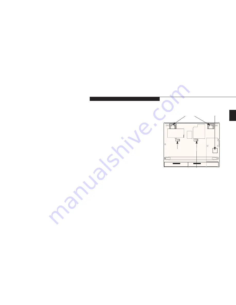
BOTTOM COMPONENTS
Tilt Adjustment Feet
These are a pair of feet which flip down and
hold the back of the notebook approximately
6° higher than the front when resting on a flat
surface. They are designed to make using your
notebook keyboard more comfortable.
(Figure 1-11.)
Memory Upgrade Compartment
This compartment houses the memory upgrade
module which allows you to expand the system
memory capacity of your notebook.
(See pages
80-83 for more information on installing added
memory capacity.) (Figure 1-11.)
Main Unit and Configuration Label
This label shows the model number and other
information about your notebook. In addition
the configuration portion of the label has the
serial number and manufacturer information
that you will need to give your support repre-
sentative so that he or she can help you. It iden-
tifies the exact version of various components
of your notebook.
(Figure 1-11.)
Figure 1-11 LifeBook E Series Bottom
Memory
Upgrade
Compartment
Tilt
Adjustment
Feet
Main Unit
Label
Multi-function Bay 1
Release Button
Multi-function Bay 2
Release Button
Multi-function Bay 1 Release Button
This is the release to allow removal and
installation of devices in Multi-function Bay 1.
(Figure 1-11.)
Multi-function Bay 2 Release Button
This is the release to allow removal and
installation of devices in Multi-function Bay 2.
(Figure 1-11.)
Multi-function Bay 1
This compartment is accessed from the front of
your notebook.
(See Figure 1-7 on page 6.)
Hard Drive Compartment
This compartment houses the primary
hard drive.
(See Figure 1-11.)
HDD
Compartment
Summary of Contents for Lifebook E360
Page 6: ...T a b l e o f C o n t e n t s ...
Page 9: ...LifeBook E Series from Fujitsu P r e f a c e ...
Page 142: ...I n d e x ...


