SS1807-N002
Installation
-
13/68
1.7 Installation for System Expansion
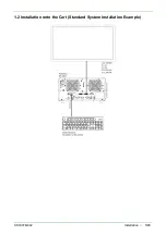
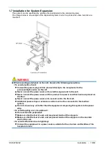
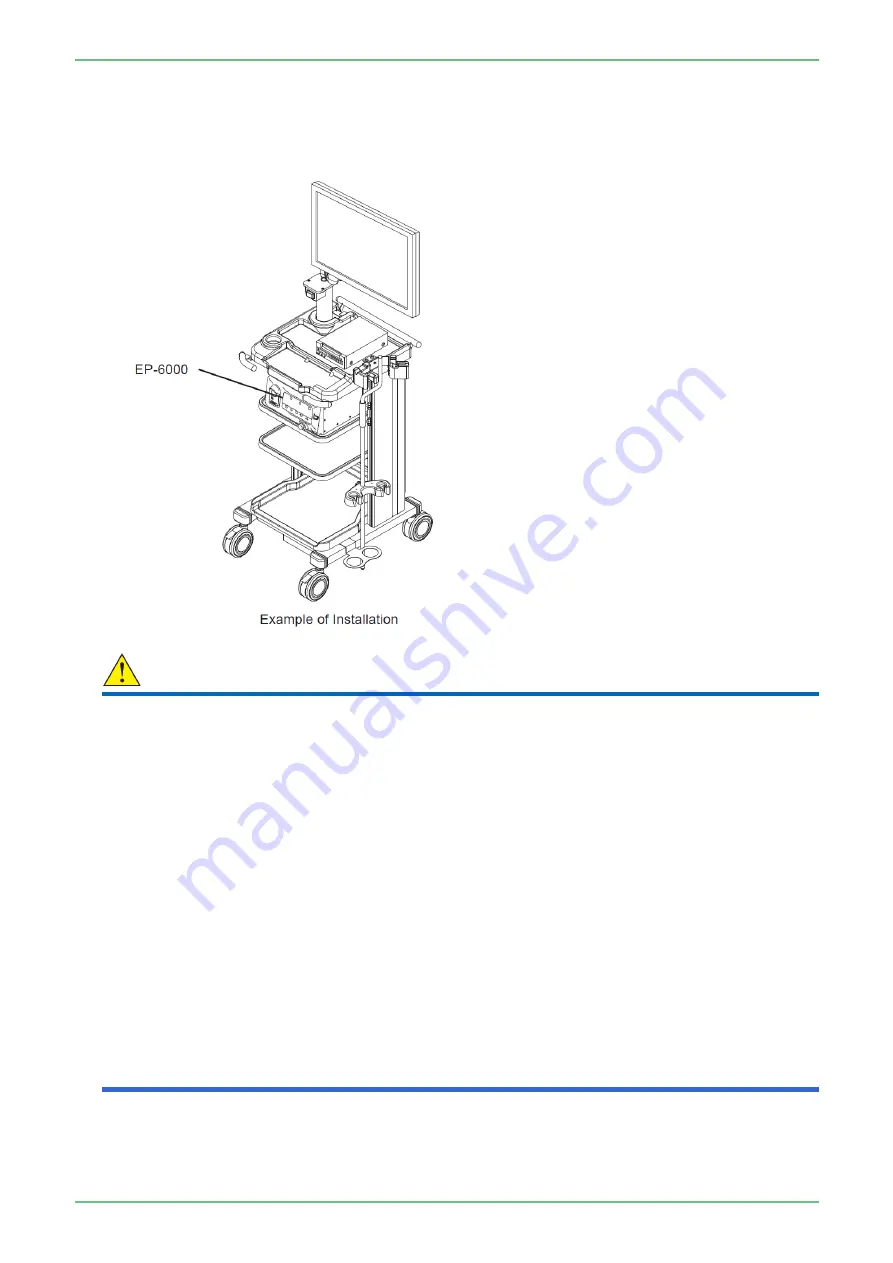
This system can be expanded by adding other peripherals to the standard system.
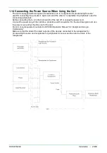
The image below is an example of the expanded system in which a printer and video recorder are
mounted.
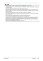
WARNING
・
When mounting peripherals on the cart, observe the following precautions.
<To avoid electric shock>
・
Connect the power plugs of this product directly to the receptacles for the
processor/light source on the cart.
・
Never connect the power source of an electrosurgical unit to the cart.
・
Never connect the power source of this product to a power cord that has been placed on
the floor.
・
Never connect the power source of a second cart to the first cart.
・
Additional power strips or extension cords must not be connected to the medical
system.
・
Do not connect any unit other than the equipment composing this system to the power
strip.
<To avoid toppling over of equipment>
・
Do not stack the peripherals.
・
Make sure that the feet of each unit are placed inside of the stoppers.
・
Make sure that the feet of each unit are placed inside of the stoppers on the movable
shelf of the cart.
<To avoid malfunction due to lightning>
・
Connect the equipment to a power source suitable for the structure and facilities of the
hospital or clinic.
Summary of Contents for EP-6000
Page 1: ...Processor EP 6000 FV693A Service Manual SR1807 N002 Ver 1 Oct 2018 ...
Page 5: ...SS1807 N002 General Table of Contents 1 1 General Table of Contents ...
Page 13: ...SS1807 N002 Caution in Safety 1 12 Caution in Safety ...
Page 25: ...SS1807 N002 Product Specifications 1 11 Product Specifications ...
Page 36: ...SS1807 N002 Instruction of System 1 106 Instruction of System ...
Page 133: ...SS1807 N002 Instruction of System 98 106 ELC PCB Patient PCB APC PCB APC PCB APC PCB DC Pump ...
Page 139: ...SS1807 N002 Instruction of System 104 106 9 4 Outline of PCB roles ...
Page 142: ...SS1807 N002 Failure Analysis 1 64 Failure Analysis ...
Page 206: ...SS1807 N002 Checkup Replacement and Adjustment 1 137 Checkup Replacement and Adjustment ...
Page 343: ...SS1807 N002 Service Parts List 1 19 Service Parts List ...
Page 352: ...SS1807 N002 Service Parts List 10 19 2 2 2 4 1 3 3 2 3 3 6 5 ...
Page 356: ...SS1807 N002 Service Parts List 14 19 1 3 3 4 1 2 1 3 X 4 1 3 3 4 3 3 ...
Page 358: ...SS1807 N002 Service Parts List 16 19 3 1 2 1 ...
Page 360: ...SS1807 N002 Service Parts List 18 19 Fig 09 5 4 2 3 1 ...
Page 362: ...SS1807 N002 Periodical Maintenance 1 15 Periodical Maintenance ...
Page 377: ...SS1807 N002 Installation 1 68 Installation ...
Page 445: ...SS1807 N002 ...

