SS1807-N002
Failure Analysi
-
11/64
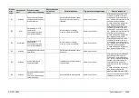
Display
error
code
Classification
level
Display message
(occurrence, response)
Display message
(guidance to
error)
Estimated cause
Trigger of message display
Service response
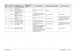
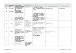
93
Error
Unplug and plug back
endoscope, reset the
processor. If the problem
persists, contact your
local FUJIFILM dealer.
Cause: It failed in
the initialization of
the panel button
and the foot
switch.
Registration of the observer for
panel switch, footswitch failed
when the power of processor
was turned on.
Same as on the left
Restart the processor.
Turn on the power at least 5
seconds after the restart.
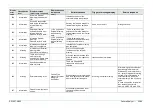
94
Error
It failed in initialization.
Restart the system.
Same as on the left
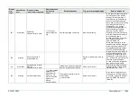
95
Error
It failed in initialization.
Restart the system.
Same as on the left
96
Error
It failed in initialization.
Restart the system.
Same as on the left
97
Error
It failed in initialization.
Restart the system.
Same as on the left
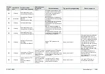
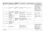
98
Information
Please press Esc key to
go back to the exam
screen for starting and
ending the exam.
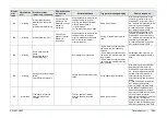
99
Information
Optical communication
will be started. OK?
100
Information
Optical communication is
underway.
101
Information
Optical communication
results: OK
102
Information
Optical communication
results: NG, 01
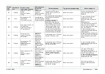
:
FCPU
port 2, port F register
reference Error
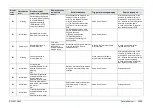
103
Information
Optical communication
results: NG, 02
:
FCPU
port 2, "VESEL EN" active
Error
104
Information
Optical communication
results: NG, 03
:
FCPU
port F, "AFE_RCLK_EN"
active Error
105
Information
Optical communication
results: NG, 04
:
IPPR
"LANE_UP status bit"
active Error
106
Information
Optical communication
results: NG, 05
:
AFE
"S600 significant bit"
active Error
Summary of Contents for EP-6000
Page 1: ...Processor EP 6000 FV693A Service Manual SR1807 N002 Ver 1 Oct 2018 ...
Page 5: ...SS1807 N002 General Table of Contents 1 1 General Table of Contents ...
Page 13: ...SS1807 N002 Caution in Safety 1 12 Caution in Safety ...
Page 25: ...SS1807 N002 Product Specifications 1 11 Product Specifications ...
Page 36: ...SS1807 N002 Instruction of System 1 106 Instruction of System ...
Page 133: ...SS1807 N002 Instruction of System 98 106 ELC PCB Patient PCB APC PCB APC PCB APC PCB DC Pump ...
Page 139: ...SS1807 N002 Instruction of System 104 106 9 4 Outline of PCB roles ...
Page 142: ...SS1807 N002 Failure Analysis 1 64 Failure Analysis ...
Page 206: ...SS1807 N002 Checkup Replacement and Adjustment 1 137 Checkup Replacement and Adjustment ...
Page 343: ...SS1807 N002 Service Parts List 1 19 Service Parts List ...
Page 352: ...SS1807 N002 Service Parts List 10 19 2 2 2 4 1 3 3 2 3 3 6 5 ...
Page 356: ...SS1807 N002 Service Parts List 14 19 1 3 3 4 1 2 1 3 X 4 1 3 3 4 3 3 ...
Page 358: ...SS1807 N002 Service Parts List 16 19 3 1 2 1 ...
Page 360: ...SS1807 N002 Service Parts List 18 19 Fig 09 5 4 2 3 1 ...
Page 362: ...SS1807 N002 Periodical Maintenance 1 15 Periodical Maintenance ...
Page 377: ...SS1807 N002 Installation 1 68 Installation ...
Page 445: ...SS1807 N002 ...


