SS1807-N002
Periodical Maintenance
-
14/15
3.3
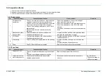
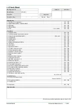
Check Sheet
Management No.
Inspector
Authorizer
Model Name
EP-6000
Serial No.
Judgment
Inspection Day
/ /
Passed
・
Reject.
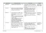
Appearance
1. All sides of the equipment
OK
・
NG
2.
Specification plate / Caution label
OK
・
NG
3. FOE label
OK
・
NG
4.
Silk printing
OK
・
NG
5. Fuse
T3.15A H250V
OK
・
NG
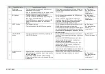
Functions
1. Dustproof Filter
OK
・
NG
2. To attach & detach electrical connector
OK
・
NG
3. Scope connection/disconnection
-22N
~
-43N
OK
・
NG
4. Power button
OK
・
NG
5. EXAM. button
OK
・
NG
6. Light button
OK
・
NG
7. Brightness Adjustment Button
OK
・
NG
8. Iris button
OK
・
NG
9. Multi button
OK
・
NG
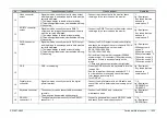
10.Light mode button
OK
・
NG
11. S video connector output
OK
・
NG
12. Video connector output
OK
・
NG
13. RGB TV connector output
OK
・
NG
14. DVI-D connector output
OK
・
NG
15.FICE
OK
・
NG
16. Digital printer connector
OK
・
NG
17. Keyboard connector
OK
・
NG
18.RS-232C connector 1 / 2
OK
・
NG
19. Network connector
OK
・
NG
20. Remote connector 1 / 2
OK
・
NG
21. Foot switch connector
OK
・
NG
22. Electronic magnification level (cursor)
OK
・
NG
23. To attach & detach external memory
OK
・
NG
24. Recording to memory
OK
・
NG
25. LG detection sensor
OK
・
NG
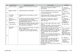
26. Brightness Adjustment
OK
・
NG
27. Maximum output light quantity
About 192unit4
unit4
28.PUMP button
29. Pump air supply pressure
Pressure 50±10kPa
kPa
30. Air guide connection
OK
・
NG
31. Software Ver.
32. Keyboard
OK
・
NG
Special notes
Write down prescribed particulars special notes for NG
Summary of Contents for EP-6000
Page 1: ...Processor EP 6000 FV693A Service Manual SR1807 N002 Ver 1 Oct 2018 ...
Page 5: ...SS1807 N002 General Table of Contents 1 1 General Table of Contents ...
Page 13: ...SS1807 N002 Caution in Safety 1 12 Caution in Safety ...
Page 25: ...SS1807 N002 Product Specifications 1 11 Product Specifications ...
Page 36: ...SS1807 N002 Instruction of System 1 106 Instruction of System ...
Page 133: ...SS1807 N002 Instruction of System 98 106 ELC PCB Patient PCB APC PCB APC PCB APC PCB DC Pump ...
Page 139: ...SS1807 N002 Instruction of System 104 106 9 4 Outline of PCB roles ...
Page 142: ...SS1807 N002 Failure Analysis 1 64 Failure Analysis ...
Page 206: ...SS1807 N002 Checkup Replacement and Adjustment 1 137 Checkup Replacement and Adjustment ...
Page 343: ...SS1807 N002 Service Parts List 1 19 Service Parts List ...
Page 352: ...SS1807 N002 Service Parts List 10 19 2 2 2 4 1 3 3 2 3 3 6 5 ...
Page 356: ...SS1807 N002 Service Parts List 14 19 1 3 3 4 1 2 1 3 X 4 1 3 3 4 3 3 ...
Page 358: ...SS1807 N002 Service Parts List 16 19 3 1 2 1 ...
Page 360: ...SS1807 N002 Service Parts List 18 19 Fig 09 5 4 2 3 1 ...
Page 362: ...SS1807 N002 Periodical Maintenance 1 15 Periodical Maintenance ...
Page 377: ...SS1807 N002 Installation 1 68 Installation ...
Page 445: ...SS1807 N002 ...

