SS1807-N002
Checkup, Replacement and Adjustment
-
113/137
No.
Inspection items
Inspection specification
How to inspect
Remarks
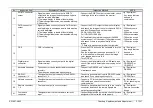
3
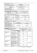
4)Patient leakage
current III
Single fault
condition
The value should be below
the value shown in [Table 5].
1) Set the test voltage to the power input
and frequency in [Table 4].
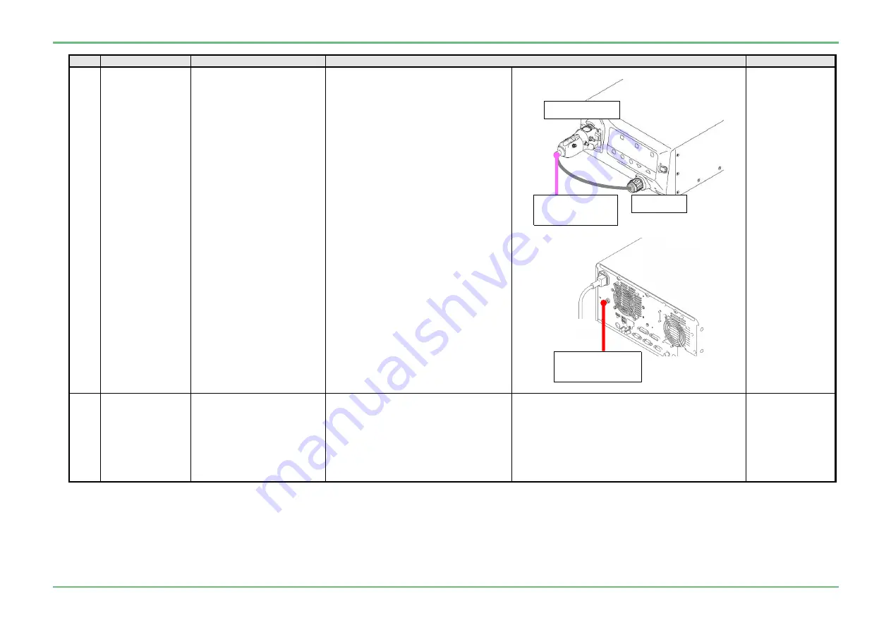
2) Connect the “842Y130002*” jig and
“J57722” jig to the processor
3) Connect the probe on applied voltage
side of the leakage current tester to the
“842Y130002*” jig and the “J57722” jig.
4) Connect the probe on leakage current
tester to the "potential equalization
terminal"
(Not necessary if the tester using the
earth Pin of power plug is used for
measurement.)
5) Turn ON the power to the device to be
measured and leave as is for 5
minutes or more.
6) Apply the test voltage and read the
leakage current value in each state.
7) Return the applied voltage to 0V, and
disconnect all cables.
* The measurement condition refers to
[Table 5].
JIG/Equipment
・
Leakage current
tester
・
842Y130002*
・
J57722
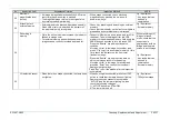
4
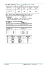
Electric current
Must be +10% or less in
relation to the center of the
specification of [Table 4].
1) Set the test voltage to the power input
and frequency in [Table 6].
2) Connect the 760 scope and each
signal output, and turn ON the power.
3) Set the light quantity to MAX and the
pump to high, leave in this state for 1
minute, and read the electric current
value.
JIG/Equipment
・
760 Scope
J57722
Probe on applied
voltage side
842Y130002*
Probe on leakage
current
tester
Summary of Contents for EP-6000
Page 1: ...Processor EP 6000 FV693A Service Manual SR1807 N002 Ver 1 Oct 2018 ...
Page 5: ...SS1807 N002 General Table of Contents 1 1 General Table of Contents ...
Page 13: ...SS1807 N002 Caution in Safety 1 12 Caution in Safety ...
Page 25: ...SS1807 N002 Product Specifications 1 11 Product Specifications ...
Page 36: ...SS1807 N002 Instruction of System 1 106 Instruction of System ...
Page 133: ...SS1807 N002 Instruction of System 98 106 ELC PCB Patient PCB APC PCB APC PCB APC PCB DC Pump ...
Page 139: ...SS1807 N002 Instruction of System 104 106 9 4 Outline of PCB roles ...
Page 142: ...SS1807 N002 Failure Analysis 1 64 Failure Analysis ...
Page 206: ...SS1807 N002 Checkup Replacement and Adjustment 1 137 Checkup Replacement and Adjustment ...
Page 343: ...SS1807 N002 Service Parts List 1 19 Service Parts List ...
Page 352: ...SS1807 N002 Service Parts List 10 19 2 2 2 4 1 3 3 2 3 3 6 5 ...
Page 356: ...SS1807 N002 Service Parts List 14 19 1 3 3 4 1 2 1 3 X 4 1 3 3 4 3 3 ...
Page 358: ...SS1807 N002 Service Parts List 16 19 3 1 2 1 ...
Page 360: ...SS1807 N002 Service Parts List 18 19 Fig 09 5 4 2 3 1 ...
Page 362: ...SS1807 N002 Periodical Maintenance 1 15 Periodical Maintenance ...
Page 377: ...SS1807 N002 Installation 1 68 Installation ...
Page 445: ...SS1807 N002 ...


