SS1807-N002
Failure Analysi
-
17/64
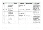
Display
error
code
Classification
level
Display message
(occurrence, response)
Display message
(guidance to
error)
Estimated cause
Trigger of message display
Service response
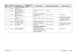
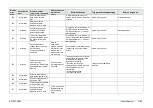
169
Information
Patient's ID has not been
entered yet.
198
Critical error
A processor error is
detected. (Please contact
a Service Center)
At startup, an error in FPGA
occurred.
At startup
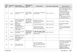
201
Information
Internal Memory will be
initialized.
All data in Internal
Memory will be deleted.
OK?
"Initialization of internal memory"
was selected in the setting for
internal memory
Same as on the left
Dialog selection→
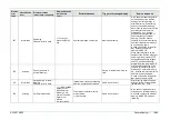
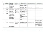
202
Information
Initializing Internal
Memory.
Please wait for a while.
“Yes” was selected in the above
dialog.
Same as on the left
Wait till initialization is finished
* Do not cancel initialization
If initialization is not completed,
replace the main PCB
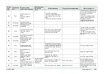
203
Information
Initialization of Internal
Memory is completed.
Initialization of internal memory
was normally completed
Same as on the left
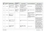
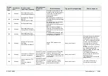
204
Warning
Initialization of Internal
Memory failed.
Initialization of internal memory
(mount) failed
Same as on the left
If initialization of internal memory
is not completed, replace the
main PCB.
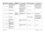
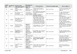
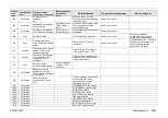
205
Information
Free space of Internal
Memory is insufficient.
The number of images that can
be recorded in media became 20
or less when the warning
message display was set to On
in the setting of internal memory
recording. Saving stops when the
message is displayed.
Same as on the left
Dialog selection→
Summary of Contents for EP-6000
Page 1: ...Processor EP 6000 FV693A Service Manual SR1807 N002 Ver 1 Oct 2018 ...
Page 5: ...SS1807 N002 General Table of Contents 1 1 General Table of Contents ...
Page 13: ...SS1807 N002 Caution in Safety 1 12 Caution in Safety ...
Page 25: ...SS1807 N002 Product Specifications 1 11 Product Specifications ...
Page 36: ...SS1807 N002 Instruction of System 1 106 Instruction of System ...
Page 133: ...SS1807 N002 Instruction of System 98 106 ELC PCB Patient PCB APC PCB APC PCB APC PCB DC Pump ...
Page 139: ...SS1807 N002 Instruction of System 104 106 9 4 Outline of PCB roles ...
Page 142: ...SS1807 N002 Failure Analysis 1 64 Failure Analysis ...
Page 206: ...SS1807 N002 Checkup Replacement and Adjustment 1 137 Checkup Replacement and Adjustment ...
Page 343: ...SS1807 N002 Service Parts List 1 19 Service Parts List ...
Page 352: ...SS1807 N002 Service Parts List 10 19 2 2 2 4 1 3 3 2 3 3 6 5 ...
Page 356: ...SS1807 N002 Service Parts List 14 19 1 3 3 4 1 2 1 3 X 4 1 3 3 4 3 3 ...
Page 358: ...SS1807 N002 Service Parts List 16 19 3 1 2 1 ...
Page 360: ...SS1807 N002 Service Parts List 18 19 Fig 09 5 4 2 3 1 ...
Page 362: ...SS1807 N002 Periodical Maintenance 1 15 Periodical Maintenance ...
Page 377: ...SS1807 N002 Installation 1 68 Installation ...
Page 445: ...SS1807 N002 ...


