SS1807-N002
Failure Analysi
-
10/64
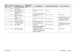
Display
error
code
Classification
level
Display message
(occurrence, response)
Display message
(guidance to
error)
Estimated cause
Trigger of message display
Service response
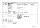
81
Information
Machinery common
config data file will be
saved in External
Memory.
OK?
Saving of machinery common
conf. setting files was selected
for backup of the service menu.
Same as on the left
Dialog selection→
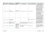
82
Information
Machinery common
config data file will be
loaded from External
Memory.
After loading, system
restart is required. OK?
Loading of machinery common
conf. setting files was selected
for backup of the service menu.
Same as on the left
Dialog selection→
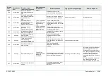
83
Information
SC reserve 83
84
Error
SC reserve 84
85
Information
530 Complementary
Color scope data will be
created.
OK?
530TV data creation button was
pressed on the service screen.
Same as on the left
Dialog selection→
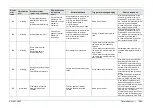
86
Information
Writing will be executed.
OK?
Writing of gain was selected on
manual color adjustment screen.
Same as on the left
Dialog selection→
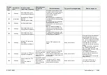
87
Information
Destination will be
changed. OK?
After the change, system
restart is required.
Same as on the left
Dialog selection→
88
Error
File not found in
destination setting
directory.
Check the destination file.
File is not found in destination
setting directory
Same as on the left
Install a correct image parameter
file.
In case of repetitive failures after
such installation, replace the
main PCB.
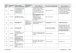
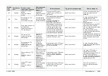
89
Information
Setting destination.
Please wait for a while.
Same as on the left
90
Information
Setting destination is
completed.
Turn off and on the power.
Writing destination files was
completed.
Same as on the left
91
Warning
Setting destination has
failed.
Writing destination files failed.
Same as on the left
92
Warning
Fan abnormality
detection.→Fan function
may be failing. The device
is still usable, but please
contact a Service Center.
Cause: Error
occurred in Fan
device.
Fan is stopped.
Same as on the left
Check fan power connector.
Summary of Contents for EP-6000
Page 1: ...Processor EP 6000 FV693A Service Manual SR1807 N002 Ver 1 Oct 2018 ...
Page 5: ...SS1807 N002 General Table of Contents 1 1 General Table of Contents ...
Page 13: ...SS1807 N002 Caution in Safety 1 12 Caution in Safety ...
Page 25: ...SS1807 N002 Product Specifications 1 11 Product Specifications ...
Page 36: ...SS1807 N002 Instruction of System 1 106 Instruction of System ...
Page 133: ...SS1807 N002 Instruction of System 98 106 ELC PCB Patient PCB APC PCB APC PCB APC PCB DC Pump ...
Page 139: ...SS1807 N002 Instruction of System 104 106 9 4 Outline of PCB roles ...
Page 142: ...SS1807 N002 Failure Analysis 1 64 Failure Analysis ...
Page 206: ...SS1807 N002 Checkup Replacement and Adjustment 1 137 Checkup Replacement and Adjustment ...
Page 343: ...SS1807 N002 Service Parts List 1 19 Service Parts List ...
Page 352: ...SS1807 N002 Service Parts List 10 19 2 2 2 4 1 3 3 2 3 3 6 5 ...
Page 356: ...SS1807 N002 Service Parts List 14 19 1 3 3 4 1 2 1 3 X 4 1 3 3 4 3 3 ...
Page 358: ...SS1807 N002 Service Parts List 16 19 3 1 2 1 ...
Page 360: ...SS1807 N002 Service Parts List 18 19 Fig 09 5 4 2 3 1 ...
Page 362: ...SS1807 N002 Periodical Maintenance 1 15 Periodical Maintenance ...
Page 377: ...SS1807 N002 Installation 1 68 Installation ...
Page 445: ...SS1807 N002 ...


