SS1807-N002
Failure Analysi
-
37/64
Display
error
code
Classification
level
Display message
(occurrence, response)
Display message
(guidance to
error)
Estimated cause
Trigger of message display
Service response
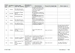
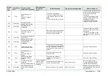
9029
Warning
Could not send beginning
notification of MPPS.
Send it again?
Communication failure to MPPS
server
Same as on the left
Check the network connection
and setting.
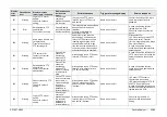
9030
Warning
Time-out error occurred.
Check the Time-out value
of DICOM Basic Settings.
When connection confirmation
failed
Wrong setting of timeout, etc.
When connection confirmation
was finished after
pressing ”Verify” on DICOM
setting screen (for service)
(failure route)
Re-check timeout setting, etc.
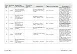
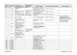
9031
Warning
DICOM transfer is not
available with the current
setting. For a DICOM
transfer, select "Use" "the
DICOM setting"
DICOM file transfer was tried
from the search screen without
DICOM being used.
Same as on the left
Re-select transfer data, and
review DICOM setting for users
and for service.
9032
Information
The modality worklist is
not selected.
Please check patient
information.
The first photographs after
inspection start was implemented
with patient information not
selected.
Same as on the left
Select inspection information
again and conduct inspection on
the inspection list screen or the
patient information input screen.
9033
Information
DICOM reserve 5
DICOM reserve
Same as on the left
9034
Information
DICOM reserve 6
DICOM reserve
Same as on the left
9035
Information
DICOM reserve 7
DICOM reserve
Same as on the left
9036
Information
DICOM reserve 8
DICOM reserve
Same as on the left
9037
Information
DICOM reserve 9
DICOM reserve
Same as on the left
9038
Information
DICOM reserve 10
DICOM reserve
Same as on the left
9039
Information
DICOM reserve 11
DICOM reserve
Same as on the left
9040
Information
DICOM reserve 12
DICOM reserve
Same as on the left
9041
Information
DICOM reserve 13
DICOM reserve
Same as on the left
9042
Information
DICOM reserve 14
DICOM reserve
Same as on the left
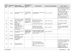
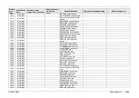
20001
Error
Unplug and plug back
endoscope, reset the
processor. If the problem
persists, contact your
local FUJIFILM dealer.
Cause: Processor
is in abnormal
state.
(1) Failure of the patient PCB
(2) Poor connection with the
patient PCB
At the time of communication
with the patient PCB
In case of repetitive failures,
replace the main PCB and the
patient PCB.
20002
Information
Iris timer is activated and
the amount of light is
being decreased.
To resume examination,
press the FR (Freeze)
switch on the scope.
While the iris timer function was
ON, the brightness variation did
not exceed the threshold value
for more than one minute.
Same as on the left
For re-starting the examination,
press the FR (Freeze) switch on
the scope.
20003
Warning
Connect or disconnect the
scope when the scope
button lights orange or
when the power is OFF.
The scope was removed during
examination.
Same as on the left
In case of repetitive failures in
spite of the scope not being
removed, replace the scope
connector and the scope.
Summary of Contents for EP-6000
Page 1: ...Processor EP 6000 FV693A Service Manual SR1807 N002 Ver 1 Oct 2018 ...
Page 5: ...SS1807 N002 General Table of Contents 1 1 General Table of Contents ...
Page 13: ...SS1807 N002 Caution in Safety 1 12 Caution in Safety ...
Page 25: ...SS1807 N002 Product Specifications 1 11 Product Specifications ...
Page 36: ...SS1807 N002 Instruction of System 1 106 Instruction of System ...
Page 133: ...SS1807 N002 Instruction of System 98 106 ELC PCB Patient PCB APC PCB APC PCB APC PCB DC Pump ...
Page 139: ...SS1807 N002 Instruction of System 104 106 9 4 Outline of PCB roles ...
Page 142: ...SS1807 N002 Failure Analysis 1 64 Failure Analysis ...
Page 206: ...SS1807 N002 Checkup Replacement and Adjustment 1 137 Checkup Replacement and Adjustment ...
Page 343: ...SS1807 N002 Service Parts List 1 19 Service Parts List ...
Page 352: ...SS1807 N002 Service Parts List 10 19 2 2 2 4 1 3 3 2 3 3 6 5 ...
Page 356: ...SS1807 N002 Service Parts List 14 19 1 3 3 4 1 2 1 3 X 4 1 3 3 4 3 3 ...
Page 358: ...SS1807 N002 Service Parts List 16 19 3 1 2 1 ...
Page 360: ...SS1807 N002 Service Parts List 18 19 Fig 09 5 4 2 3 1 ...
Page 362: ...SS1807 N002 Periodical Maintenance 1 15 Periodical Maintenance ...
Page 377: ...SS1807 N002 Installation 1 68 Installation ...
Page 445: ...SS1807 N002 ...

