Installing the Access Point
62
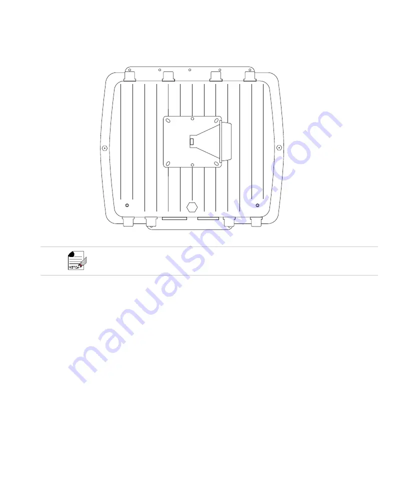
Figure 37:
Square Mounting Bracket Attaches to Bottom of OAP433e
6.
Insert the circular portion of the bracket attached to the AP into the hollow cone portion of
the bracket on the wall. The two should fit somewhat snugly, although a screw assembly
will be required to hold them in place.
7.
Run one of the long screws provided in the package down through the hole that runs
through both portions of the bracket. The head of the screw should fit into the hexagonal
slot on the top of the bracket assembly.
8.
On the other end of the screw (i.e., the one that doesn’t have the hexagonal head), slide a
flat washer and then a lock washer into place. The flat washer should be against the base
of the mounting assembly.
9.
Screw one of the hexagonal nuts into place on top of the two washers. Once tightened,
the nut should force the lock washer into place and the two bracket components should
be locked together.
10.
Connect the Ethernet cable to the controller and verify that all antennas are securely con-
nected.
Note that the circular portion of the bracket should be facing to the side of the AP (the AP’s sides are
the faces that do not have antennas or other attachments). This is to ensure that the AP is properly ori-
ented when the bracket is fully assembled.
Summary of Contents for AP400 Series
Page 26: ...Table of Contents xii...
Page 30: ...Contacting Fortinet 16...
Page 33: ...AP400 19 Figure 2 AP433e Figure 3 AP433i is RESET CONSOLE G1 USB 00258 00275...
Page 34: ...AP400 20 Figure 4 OAP433e Outdoor Access Point top and bottom...
Page 52: ...Where to Go From Here 38...
Page 66: ...Where to Go From Here 52...
Page 80: ...Where to Go From Here 66...
Page 86: ...Warnings 72...
Page 98: ...Manufacturing Information 84...
Page 100: ...Supported Power Over Ethernet Devices for Fortinet APs 86...
Page 102: ...88...