


Install the AP433e
28
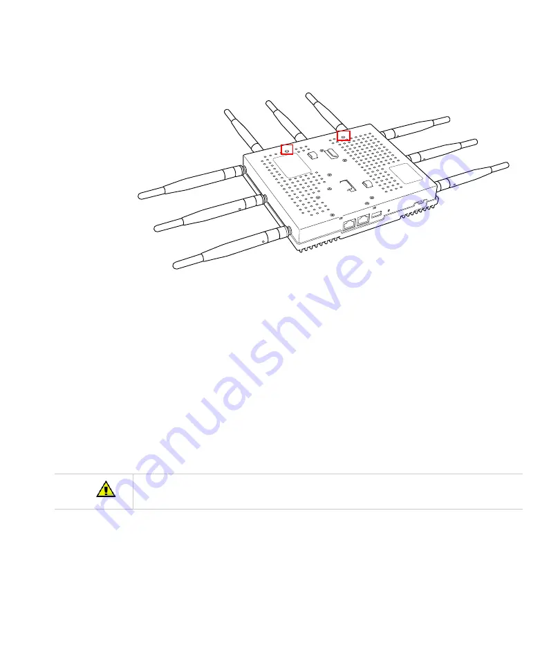
Figure 8:
AP Mounting Screw Holes
7.
Orient the AP433e horizontally so that you can read the Fortinet logo and the Console
and network ports are pointed downwards - this orientation provides optimum MIMO per-
formance.
8.
9.
Align the mounting screws on the back of the AP433e with the corresponding holes on the
mounting bracket.
10.
Slide the AP433e downwards until the screws click into the holes. They should seat fairly
firmly.
11.
Slide the mounting bracket’s locking bar to the right, locking the AP in place.
12.
If desired, use the provided clip to lock the bracket shut by sliding it through the aligned
holes on the right-hand side of the bracket.
13.
Attach the antennas to the AP.
14.
Connect one end of the Ethernet cable to the switch and the other end to the AP433e
Ethernet port.
00271
Be sure to connect the Ethernet cable to the Ethernet port; the cable can mistakenly be plugged into the
Console port. If you do this, the AP won’t power up.
Summary of Contents for AP400 Series
Page 26: ...Table of Contents xii...
Page 30: ...Contacting Fortinet 16...
Page 33: ...AP400 19 Figure 2 AP433e Figure 3 AP433i is RESET CONSOLE G1 USB 00258 00275...
Page 34: ...AP400 20 Figure 4 OAP433e Outdoor Access Point top and bottom...
Page 52: ...Where to Go From Here 38...
Page 66: ...Where to Go From Here 52...
Page 80: ...Where to Go From Here 66...
Page 86: ...Warnings 72...
Page 98: ...Manufacturing Information 84...
Page 100: ...Supported Power Over Ethernet Devices for Fortinet APs 86...
Page 102: ...88...


