


Installing the Access Point
61
2.
Place the ‘v’ component against the wall at the desired location and mark the four holes
(one at each corner of the bracket) on the wall.
3.
Remove the bracket and drill the corresponding holes. When finished, insert the plastic
sheetrock anchor inserts into each hole drilled.
4.
Place the bracket against the wall again and use the screws provided with the plastic
anchors to attach it to the wall.
5.
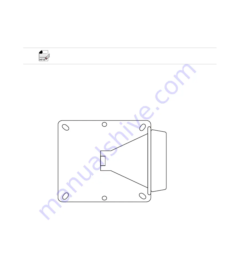
Using the portion of the bracket assembly that has a flat component attached to another
circular portion (see
), attach the OAP433e to the square portion of
the mounting bracket by placing the bracket flat against the bottom of the AP and insert-
ing screws into the corners of the bracket portion. The holes on the bracket should corre-
spond to the holes on the bottom of the AP. See
Figure 36:
Square Mounting Bracket
Note that the bracket must be oriented such that the wider portions of the bracket are its top and bottom
when placed against the wall. This will ensure that the fully deployed AP will be oriented properly (with
the Ethernet cable leading downwards).
Summary of Contents for AP400 Series
Page 26: ...Table of Contents xii...
Page 30: ...Contacting Fortinet 16...
Page 33: ...AP400 19 Figure 2 AP433e Figure 3 AP433i is RESET CONSOLE G1 USB 00258 00275...
Page 34: ...AP400 20 Figure 4 OAP433e Outdoor Access Point top and bottom...
Page 52: ...Where to Go From Here 38...
Page 66: ...Where to Go From Here 52...
Page 80: ...Where to Go From Here 66...
Page 86: ...Warnings 72...
Page 98: ...Manufacturing Information 84...
Page 100: ...Supported Power Over Ethernet Devices for Fortinet APs 86...
Page 102: ...88...


