Powering Up
Base-520(G) Installation
Page 26
SPARC/CPCI-52x(G)
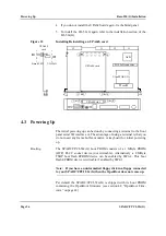
4. If you do not install the UPA64S card again, fix the blind panel.
5. To install the I/O-52xG again refer to the installation section of the
I/O-52x(G).
Figure 12
Installing/Deinstalling an UPA64S card
4.3
Powering Up
The initial powering up can be done by connecting a terminal to the front
panel serial I/O interface A. The advantage of using a terminal is that you
do not need any frame buffer, monitor, or keyboard for initial powering
up.
Booting
The SPARC/CPCI-52x(G) boot PROM consists of a 1 MByte PROM
(OTP) PLCC socket device (not writeable). Alternatively a 2 MByte
TSOP boot flash EPROM device can be enabled by SW6-2. This boot
flash EPROM device is writeable if enabled by SW4-3.
Note: If you have an unformatted floppy disk in a floppy connected
to your SPARC/CPCI-52x(G) then the OpenBoot does not come up.
Per default the SPARC/CPCI-52x(G) is shipped with its boot PROM
containing the OpenBoot firmware (see section 4.8 “OpenBoot Firm-
ware” on page 42).
UPA64S card
Top
UPA64S slot
& 2
1
& 2
1
& 4
3
& 4
3
5
6
I/O-52xG connector
UltraSPARC-IIi
L2 cache
J1
J5
J2
J3
APB
UPA64S
card
I/O-52xG
Base-520G
Summary of Contents for SPARC/CPCI-520G
Page 6: ...Contents Page iv SPARC CPCI 52x G...
Page 14: ...Using This Manual Page xii SPARC CPCI 52x G...
Page 18: ...Page 4 SPARC CPCI 52x G...
Page 20: ...Introduction Page 6 SPARC CPCI 52x G...
Page 24: ...Ordering Information Introduction Page 10 SPARC CPCI 52x G...
Page 58: ...OpenBoot Firmware Base 520 G Installation Page 44 SPARC CPCI 52x G...
Page 66: ...OpenBoot Firmware Base 520 G Installation Page 52 SPARC CPCI 52x G...
Page 102: ...Ethernet and EBus2 Devices PCIO Hardware Description Page 88 SPARC CPCI 52x G...
Page 114: ...PMC Slots with Busmode Support Hardware Description Page 100 SPARC CPCI 52x G...
Page 134: ......


