Base-520(G) Installation
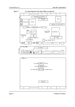
Front Panel and Connectors
SPARC/CPCI-52x(G)
Page 35
4.5.5
Keyboard/Mouse Connector
The SUN-type keyboard/mouse interface is available at the front panel
via an 8-pin mini-DIN connector.
Table 18
26-pin serial A+B connector pinout RS422 (factory option)
Signal
Pin
Connector
Pin
Signal
n.c.
1
14
CTS+_B (Input))
CTS+_A (Input))
2
15
nc
RTS–_A (Output)
3
16
RTS–_B (Output)
RTS+_A (Output)
4
17
nc
CTS–_A (Input)
5
18
nc
nc
6
19
RTS+_B (Output)
RxD–_A (Input)
7
20
RxD+_A (Input)
TxD–_A (Output)
8
21
nc
n.c.
9
22
nc
n.c.
10
23
RxD–_B (Input)
RxD+_B (Input)
11
24
TxD+_A (Output)
TxD–_B (Output)
12
25
TxD+_B (Output)
CTS–_B (Input)
13
26
n.c.
14
1
26
13
Table 19
Keyboard/mouse connector pinout
Connector
Pin
Function
1
GND
2
GND
3
+5 V DC
4
Mouse In
5
Keyboard Out
6
Keyboard In
7
Mouse Out
8
+5 V DC
4
3
5
8 7
6
2
1
Summary of Contents for SPARC/CPCI-520G
Page 6: ...Contents Page iv SPARC CPCI 52x G...
Page 14: ...Using This Manual Page xii SPARC CPCI 52x G...
Page 18: ...Page 4 SPARC CPCI 52x G...
Page 20: ...Introduction Page 6 SPARC CPCI 52x G...
Page 24: ...Ordering Information Introduction Page 10 SPARC CPCI 52x G...
Page 58: ...OpenBoot Firmware Base 520 G Installation Page 44 SPARC CPCI 52x G...
Page 66: ...OpenBoot Firmware Base 520 G Installation Page 52 SPARC CPCI 52x G...
Page 102: ...Ethernet and EBus2 Devices PCIO Hardware Description Page 88 SPARC CPCI 52x G...
Page 114: ...PMC Slots with Busmode Support Hardware Description Page 100 SPARC CPCI 52x G...
Page 134: ......


