Pro
Website
36
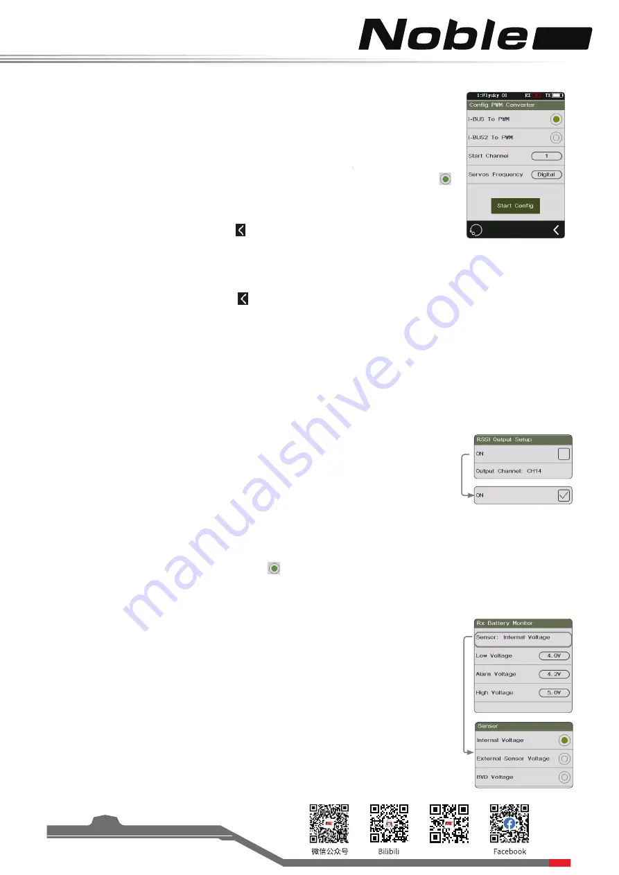
7.9 Config PWM Converter
This function allows you to configure the corresponding receiver to a PWM converter
(hereinafter referred to as a secondary receiver)
.
Setup:
Note: Shut down the receiver.
1. Set the receiver to the bind state.
2. Turn on the transmitter. Enter the [Config PWM Converter] menu. Click the right side
of [i-BUS to PWM].This function allows you to configure the corresponding receiver to a
PWM converter
(hereinafter referred to as a secondary receiver)
.
3. Click [Start channel] to enter the submenu and select the corresponding channel as the
first interface output of the receiver. Click to return to the previous level interface.
7.10 RSSI Output Setup
This function is used to set the channel of transmitter output signal strength, and transmit
the signal strength to the model through the channel.
• The range of the transmitter signal strength is 0-100.
• When the signal strength is 0, the signal strength may still be calculated or the
transmitter does not receive the signals from the receiver.
• After setting the channel, the channels corresponding to PWM, PPM, i-BUS out, and
S.BUS indicate the signal strength. It will be invalid if the channel is assigned with
other functions.
7.11 RX Battery Monitor
This function is used to detect the voltage status of the receiver battery. Set the high
and low battery voltages according to the actual usage of the receiver battery and
the remaining battery level displayed through the icon in the upper right corner. The
transmitter will promptly send an alarm according to battery conditions.
When the receiver battery voltage is lower than the [Alarm voltage] alarm value, the
transmitter will report "The receiver voltage is low".
[Sensor]: The voltage of the Voltage sensor is used as the voltage of the receiver. [Internal
Voltage], [External Sensor Voltage] or [BVD Voltage] can be selected. After selection, it can
be displayed and alarmed through the transmitter.
Setup:
1. Click [External Sensor] to select an internal or external sensor.
2. Set the [Low voltage], [alarm voltage], and [high voltage] values.
•
[Low Voltage]: The voltage corresponding to Receiver battery level is 0%; [High
Voltage]: The voltage corresponding to Receiver battery level is 100%.
4. Click [Servos Frequency] to enter the submenu. Click the corresponding option on the right side. You can
customize the frenquency of the servo. The range can be50 Hz to 400 Hz.
• When you select i-BUS2 to PWM, the operations of steps 2 and 3 are not required.
5. Click [Start Config]. The system will enter bind status. The secondary receiver indicator will flash twice and go off.
It indicates successful configuration. Click to manually return to the previous level interface.
6. RX re-enters the bind state to complete the bind with TX. After successful, the receiver can resume normal use.
•
Confirm that only new port A selects i-BUS2 signal.
•
When i-BUS2 receiver operates as the secondary system, the channel assignment and servo response speed are
set under i-BUS2 HUB menu.
•
If you perform a re-bind, the secondary receiver parameters will be invalid. Re-configuration is required when it
operates as the secondary receiver again.
Setup:
1. Select the check box on the right side of [On] to enable this function.
2. Click [Output Channel] to select the right side of the corresponding channel.


