


Instruments/controls - Cab
2020-01-06
4812314580EN
43
Ventilation
The controller has two ventilation modes: manual and automatic
ventilation.
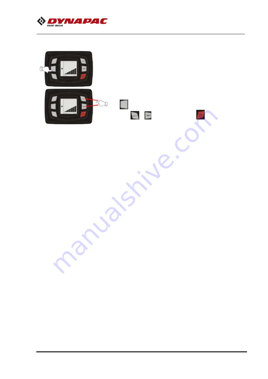
Manual ventilation
The manual ventilation has three speeds. When some function
(cooling, heating or automatic mode) is active, the ventilation
function is always on. To change the fan speed, press the key
(Ventilation mode) and after set the desired speed with the
keys
or
.
After press the key
to confirm or wait a
few seconds and the speed will be saved
.
Summary of Contents for Dynapac CP2100
Page 2: ......
Page 3: ......
Page 5: ......
Page 6: ......
Page 9: ...Introduction 2020 01 06 4812314580EN 3...
Page 17: ...Technical specifications 2020 01 06 4812314580EN 11...
Page 24: ...Safety decals description and location 18 4812314580EN 2020 01 06...
Page 29: ...Instrument controls Description and function 2020 01 06 4812314580EN 23...
Page 36: ...Instrument controls Description and function 30 4812314580EN 2020 01 06...
Page 39: ...Instrument controls Description and function 2020 01 06 4812314580EN 33...
Page 46: ...Emergency procedures 40 4812314580EN 2020 01 06...
Page 50: ...Instruments controls Cab 44 4812314580EN 2020 01 06...
Page 67: ...Operation 2020 01 06 4812314580EN 61...
Page 75: ...Transport 2020 01 06 4812314580EN 69...
Page 77: ...Operation instructions Overview 2020 01 06 4812314580EN 71...
Page 79: ...Preventive maintenance 2020 01 06 4812314580EN 73...
Page 91: ...Scheduled maintenance and lubrication 2020 01 06 4812314580EN 85...
Page 106: ...Maintenance Every 50 hours 100 4812314580EN 2020 01 06...
Page 129: ......


