


February 2017
www.farmscanag.com
AM-74V1-4
35
Machine Setup
AUXILIARY SETUP / DUMP VALVE (1B)
By default, the 74V1 will select the output/ valve configuration depending on what number of sections
(available outputs) the UniPOD was purchased with. However, Auxiliary Setup allows the user to customise
which output control goes to which valve or sensor. This is required to be setup when using a DUMP Valve.
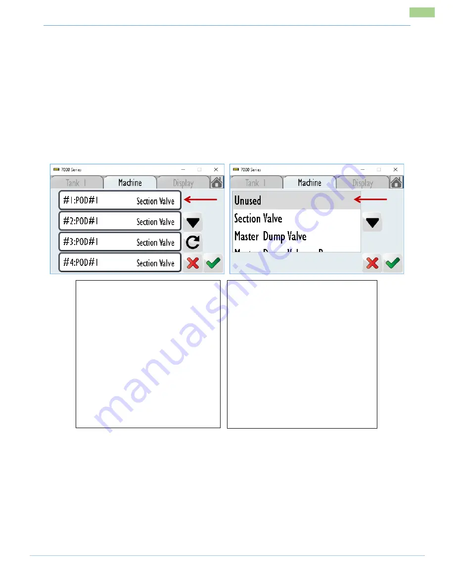
When multiple UniPOD’s are connected you can easily identify the POD #.
Select the output number that you want to change.
A selection of available valves/ sensors will be displayed.
Select the valve/sensor type required.
Select the green Tick button to save changes.
^ Select this if the Master Dump is Opening when it should be closing or Vice Versa
^^ Select this if the Dump is Opening when it should be closing or Vice Versa
** When enabling 2
nd
Line – Note the Auxiliary on the harness you are connected to. Select this option.
When prompted – Ensure you select LINE 2
NOTES:
Each UniPOD has 10 selectable outputs. Add a 2
nd
UniPOD for 20 outputs.
When multiple UniPODS are connected on the CANbus line the POD# will change. E.g. #11:POD#2
If you have purchased a 5 section harness (AC-7405) you will have 5 o Dump.
If you have purchased a 10 Section harness (AC-7410) you will have 10 outputs in total to configure
Options available are:
Section Valve
Master Dump Valve
Master Dump Valve (Reverse) ^
Dump Valve
Dump Valve (Reverse) ^^
Spray Line Valve **
Left Marker Arm
Right Marker Arm
Master Level Input
Level Input
Example (AC-7405) – 5 Section Harness
Refer to labelling on Harness
#1:POD#1 : Section Valve
#2:POD#1 : Section Valve
#3:POD#1 : Section Valve
#4:POD#1 : Section Valve
#5:POD#1 : Section Valve
#6:POD#1 : Master Dump Valve
This assumes a Master Dump Valve is
installed