


Installation
8.
INSTAL
LAT
ION
System installation
302
Ref.2003
· 248 ·
QC-PDS
HARDWARE
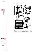
A18. Under cover +24 V DC terminals.
For power supplies, drives, bus protection modules and capacitor
modules.
X14. Basic control signals.
For QC-PS-
non-regenerative power supplies.
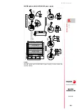
X5. Software transfer and/or adjustment process of the axis through a
RS-232 serial line from the WinDDSSetup application for a PC or laptop.
Only for the QC-DR-275-
S
S2 drive and QC-RPS-160-
S
N0 main power
supply
X13A. Feed axis or spindle STO
·
Safe Torque Off
·
for single-drives.
X13A/X13B. STO for each feed axis or spindle
·
Safe Torque Off
·
for
dual-drives.
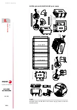
X33. Soft-Start activation.
For a QC-APS3-15 auxiliary power supply.
X34. SBC for the feed axis brake
·
Safe Brake Control
·
For the QC-DR-275-
S
S2 drive.
X35. Basic control signals
For the QC-RPS-160-
S
N0 regenerative power supply.
X60. Line voltage feedback.
For regenerative main power supplies.
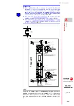
Connection to the central point of the protective earth.
For each of the chassis of the units that make up the entire QC-PDS
system.
Electrical precautions
MANDATORY.
For protection against high leak currents (3.5 mA AC or
10 mA DC), use a protective earth conductor with a cross-section of at
least S/2, where S (mm²) is the cross section of the conductors connected
to the power supply terminals.
For S (mm²) that are up to and including 35 mm², use a protective earth
conductor with a cross section of at least 10 mm² (Cu) or 16 mm² (Al) or
two protective earth conductors with the same cross section as that of the
wires connected to the power supply terminals.
When making protective earth connections, ensure to comply with local
standards. Note the symbol indicating this precaution indicated by an
arrow in figure
F. H8/9
Precaution against high leakage currents. Warning symbol on the upper part of
the units.
WARNING.
The system must always be installed before applying voltage
according to the EN 60204-1 standard. Ignoring it may cause serious
injuries, even death.
Summary of Contents for QC-PDS
Page 1: ...DRIVE QC PDS Hardware manual Ref 2003...
Page 6: ...6 I 6 Ref 2003 6 QC PDS HARDWARE This page intentionally left blank...
Page 16: ...16 Ref 2003 16 Previous I QC PDS HARDWARE This page intentionally left blank...
Page 18: ...18 Ref 2003 18 Previous II QC PDS HARDWARE This page intentionally left blank...
Page 80: ...2 POWER SUPPLIES Power supplies 80 Ref 2003 QC PDS HARDWARE...
Page 138: ...3 DRIVES Drives 138 Ref 2003 QC PDS HARDWARE...
Page 174: ...4 AUXILIARY MODULES Auxiliary modules Ref 2003 174 QC PDS HARDWARE...
Page 302: ...8 INSTALLATION Installation Ref 2003 302 QC PDS HARDWARE...
Page 366: ...12 COMMERCIAL MODELS Commercial models Ref 2003 QC PDS HARDWARE 366...
Page 367: ...ANNEXES...
Page 368: ...ANNEX A1...
Page 383: ...ANNEX A2...
Page 398: ...ANNEX A3...
Page 418: ......
Page 419: ......


