


Installation
8.
INSTAL
LAT
ION
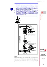
Locatio
n
302
Ref.2003
· 240 ·
QC-PDS
HARDWARE
EMC instructions for equipment installation
Use equipotential wires in systems with:
MANDATORY.
Use the plates that are provided as accessories when mounting.
Make the connections with wide contact surfaces for the metal parts.
Remove the paint from contact surfaces.
Try to increase conductivity on two-dimensional contacts.
Install a protection circuit if there is a risk of over-voltage.
Keep electrical power supply lines away from signal lines.
Note. Electric fields can induce voltage peaks in signal lines, which
decreases when there is more distance between them.
Keep the motor power cable at least 20 cm away from the signal cable
or use shielding on both the motor cable and signal cable.
Do not run field bus cables and signal through a single conduit with DC
and AC lines with voltages over 60 V. The field bus cables, signal lines
and analog lines can be installed in a same conduit. Recommendation.
Separate the conductors where the cables are to be installed, by at
least 20 cm or at least as far away as possible. Do not install
unnecessary cable loops and use short cables from the central ground
point for connecting to a ground point outside the electrical cabinet.
Avoid induction loops by choosing common routes for power, signal and
data circuit cables.
Use shielded power cables and motor cables.
On shielded cables, the unshielded portion of the cable used to connect
them to the connectors must be as short as possible in order to reduce
radiated emissions.
MANDATORY.
Installations of large areas.
Different voltage sources.
Mains through several buildings reducing the current in the cable shield
and the emissions. Connect to ground the electrical cabinet, the door,
the mounting plate, with ground straps or cables with a cross section
larger than 10 mm² (AWG 6).
The ground shields of the digital signal wires must be connected at both
ends to a large surface or through a conductive housing of the
connector. This reduces disturbances that affect the signal cables and
also the emissions.
The ground shields of the analog signal wires must be connected
directly to the device (signal input), reducing the ground loops due to
low frequency disturbances.
When a unit does not have a ground connection, the shield connection
must be made on the side of the unit connected to ground.
Use cable and ground clamps to connect large areas of cable shield.
Mount switching devices such as contactors, relays or electro-valves
with interference suppression elements or arc suppressors (e.g. diodes,
varistors, RC circuits).
Install power and control components separately.
Install before mains and the QC-PDS system mains chokes to reduce
harmonics and expand the useful life of the product. Also, external
mains filters are installed to improve the EMC limit values.
Use equipotential cables when having long lines to reduce the current
through the cable shield.
Summary of Contents for QC-PDS
Page 1: ...DRIVE QC PDS Hardware manual Ref 2003...
Page 6: ...6 I 6 Ref 2003 6 QC PDS HARDWARE This page intentionally left blank...
Page 16: ...16 Ref 2003 16 Previous I QC PDS HARDWARE This page intentionally left blank...
Page 18: ...18 Ref 2003 18 Previous II QC PDS HARDWARE This page intentionally left blank...
Page 80: ...2 POWER SUPPLIES Power supplies 80 Ref 2003 QC PDS HARDWARE...
Page 138: ...3 DRIVES Drives 138 Ref 2003 QC PDS HARDWARE...
Page 174: ...4 AUXILIARY MODULES Auxiliary modules Ref 2003 174 QC PDS HARDWARE...
Page 302: ...8 INSTALLATION Installation Ref 2003 302 QC PDS HARDWARE...
Page 366: ...12 COMMERCIAL MODELS Commercial models Ref 2003 QC PDS HARDWARE 366...
Page 367: ...ANNEXES...
Page 368: ...ANNEX A1...
Page 383: ...ANNEX A2...
Page 398: ...ANNEX A3...
Page 418: ......
Page 419: ......


