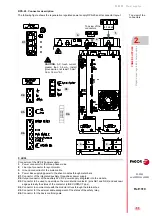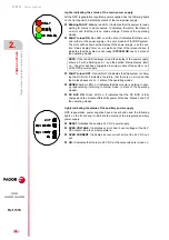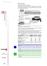
Power supplies
POWER SUPPLIES
Re
gene
rative regul
ated pow
er
su
ppli
es
2.
79
DDS
HARDWARE
Ref.1310
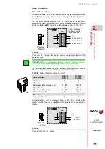
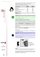
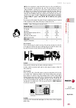
Other elements
Besides the various connectors, the front panel of these power supplies
has other elements that are mentioned next.
Status display
The 7-segment status display shows the system start-up sequence as well
as the possible errors and warnings that could come up. For further detail,
see the section “turning the module on” at the end of this chapter and go to
chapter
14. ERROR CODES AND MESSAGES
at the RPS power supplies
in the “man_dds_soft.pdf” manual to interpret the errors and/or warnings
displayed.
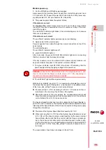
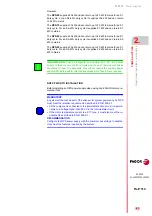
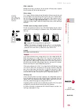
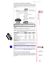
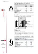
DC BUS command voltage selector switches
The two dip-switches located on top of the status display may be used to
program the DC BUS voltage to a particular value. The possible combina-
tions are:
Let's suppose that the mains voltage is 460 V AC. The voltage that the DC
BUS can supply is 1.41 x 460 = 650 V DC. Therefore, we must select a
switch setting like figure
(option 4), because any of the other set-
tings generates a BUS voltage lower than 650 V DC and the purpose is to
be able to raise the BUS voltage higher than the one mains can provide.
See the note below for switch configuration (option 1).
If the mains voltage is 430 V AC. The voltage that the DC BUS can supply
is 1.41x430 = 608 V DC. Therefore, we must select a switch setting that
sets a bus voltage higher than this value; i.e. either the one given by option
2 or the one given by option 4 of figure
. Any of these two settings
would be valid. See the note below for switch configuration (option 1).
Clarifying note
In the conclusions drawn from these examples, the configuration (option 1)
has been ignored because the bus voltage depends on the value set in pa-
rameter VP5. This parameter admits values between 500 V DC and 750 V
DC and by default it is assigned a voltage of 650 V DC.
Considering that it has been set to its default value (650 V DC), this switch
configuration could also be set in both cases of this example.
For further information on parameter VP5 of the RPS power supplies, con-
tact Fagor Automation S. Coop.
F. H2/40
Bus voltage selector switches.
Example.
STATUS
DISPLAY
ON
ON
ON
ON
ON
VP5 V DC
625 V DC
600 V DC
675 V DC
It represents the moving element of each switch.
(2)
NOTE.
If the selected configuration is the option 1, i.e. both switches
ON, the value of the bus voltage will be the one set by the user in
parameter VP5 of the RPS. By default, this value is 650 V DC.
(1)
(3)
(4)
Summary of Contents for DDS
Page 1: ...DRIVE DDS Hardware manual Ref 1310...
Page 6: ...I 6 DDS HARDWARE Ref 1310...
Page 9: ......
Page 10: ......
Page 11: ......
Page 12: ......
Page 16: ...16 Ref 1310 DDS HARDWARE...
Page 30: ...1 DESCRIPTION 30 Description DDS HARDWARE Ref 1310...
Page 94: ...2 POWER SUPPLIES 94 Power supplies DDS HARDWARE Ref 1310...
Page 188: ...3 DRIVE MODULES 188 Drive modules DDS HARDWARE Ref 1310...
Page 204: ...4 AUXILIARY MODULES 204 Auxiliary modules DDS HARDWARE Ref 1310...
Page 232: ...SELECTING CRITERIA 5 232 Selection criteria DDS HARDWARE Ref 1310...
Page 266: ...7 CABLES 266 Cables DDS HARDWARE Ref 1310...
Page 312: ...8 INSTALLATION 312 Installation DDS HARDWARE Ref 1310...
Page 326: ...9 FUNCTIONAL SAFETY 326 Functional safety DDS HARDWARE Ref 1310...
Page 354: ...10 CONNECTION DIAGRAMS 354 Connection diagrams DDS HARDWARE Ref 1310...
Page 378: ...12 SALES REFERENCES 378 Sales references DDS HARDWARE Ref 1310...
Page 384: ...13 COMPATIBILITY 384 Compatibility DDS HARDWARE Ref 1310...
Page 385: ......

