Connection diagrams
CON
N
ECTION DIAGRAMS
Di
ag
ra
ms wit
h
a PS-2
5B
4 po
we
r
su
pp
ly
10.
341
DDS
HARDWARE
Ref.1310
F. H10/13
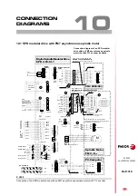
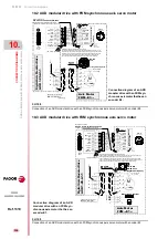
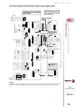
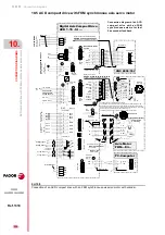
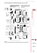
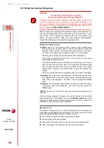
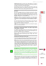
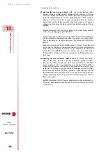
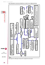
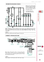
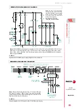
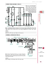
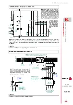
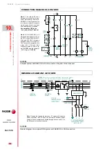
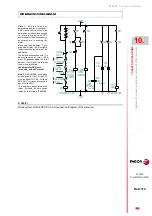
System with a PS-25B4 power supply Diagram of the maneuver.
F. H10/14
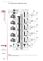
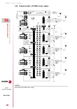
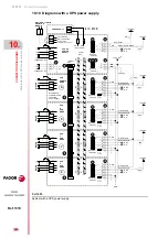
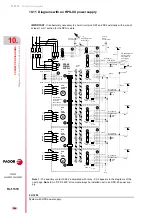
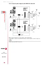
General diagram of a DDS system with a PS-25B4 power supply.
PS-25B4
SYSTEM OK
+24VDC
X+
X-
Y+
Y-
Z+
Z-
KA1
KM1
ON
KM1
EMERG.
STOP
-KA2
OFF
SYSTEM
SPEED
ENABLE
-KM1
-KA1
EMERGENCY LINE
I1 PLC
CNC EMERG.
O1 PLC
GND
ON
OFF
to SPEED ENABLES
-KA7
BRAKE
CONTROL
BRK
(See GP9)
ON
Green
OFF
Red
KA2
KA2
KA2
KA1
CNC
ENABLE
X
CNC
ENABLE
S
CNC
ENABLE
Y
CNC
ENABLE
Z
Delay off
-KA3
DRIVE
ENABLES
(See GP9)
t seconds
-KA4
-KA5
-KA6
Note.
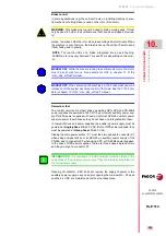
CNC EMERG. will always be assigned to I1/O1 of the PLC with an 8055/55i CNC. With an
8070 CNC, it may be assigned to any I/O of the PLC. The contacts associated with relays - KA2, -
KA3, - KA4, - KA5, - KA6 and - KA7 are shown inside a circle in figure
and the contactor -
KM1 in figure
Note.
The relay - KA3 uses delayed
deactivation (t seconds) maintaining
the DRIVE ENABLE control signal
active for a few seconds to maintain
motor torque while the vertical axis
holding brake is enabled.
See parameter GP9 in the
“man_dds_soft.pdf” manual.
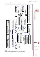
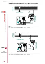
OPERATION DIAGRAM. PS-25B4
PE
- S1
MECHANICAL
MAIN SWITCH
- F3
- F4
- F5
MAINS FILTER 42A
L1
L3
L2
L1
3x400-460 VAC
2x400-460 VAC
R
S
T
R
S
T
CONTACTOR
- KM1
L2
N
- Q1
DIFFERENTIAL
BREAKER
WARNING.
When using an isolating transformer, the secondary must be
connected in star and its middle point must be connected to GND.
POWER MAINS
IT A MUST TO USE FUSES
TO THE POWER CONNECTOR
PS-25B4 POWER SUPPLY
TO THE X3 CONNECTOR
PS-25B4 POWER SUPPLY
Note.
Observe that having the main key - S1 closed, although
the power contactor - KM1 is open, the internal auxiliary
power supply remains connected through its connector X3 to
feed the control circuits of the drive.
GENERAL DIAGRAM. PS-25B4
Summary of Contents for DDS
Page 1: ...DRIVE DDS Hardware manual Ref 1310...
Page 6: ...I 6 DDS HARDWARE Ref 1310...
Page 9: ......
Page 10: ......
Page 11: ......
Page 12: ......
Page 16: ...16 Ref 1310 DDS HARDWARE...
Page 30: ...1 DESCRIPTION 30 Description DDS HARDWARE Ref 1310...
Page 94: ...2 POWER SUPPLIES 94 Power supplies DDS HARDWARE Ref 1310...
Page 188: ...3 DRIVE MODULES 188 Drive modules DDS HARDWARE Ref 1310...
Page 204: ...4 AUXILIARY MODULES 204 Auxiliary modules DDS HARDWARE Ref 1310...
Page 232: ...SELECTING CRITERIA 5 232 Selection criteria DDS HARDWARE Ref 1310...
Page 266: ...7 CABLES 266 Cables DDS HARDWARE Ref 1310...
Page 312: ...8 INSTALLATION 312 Installation DDS HARDWARE Ref 1310...
Page 326: ...9 FUNCTIONAL SAFETY 326 Functional safety DDS HARDWARE Ref 1310...
Page 354: ...10 CONNECTION DIAGRAMS 354 Connection diagrams DDS HARDWARE Ref 1310...
Page 378: ...12 SALES REFERENCES 378 Sales references DDS HARDWARE Ref 1310...
Page 384: ...13 COMPATIBILITY 384 Compatibility DDS HARDWARE Ref 1310...
Page 385: ......

