Cables
CABLES
D
irect feed
back
cabl
e
7.
253
DDS
HARDWARE
Ref.1310
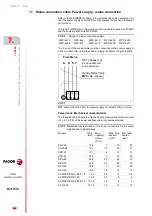
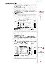
7.4 Direct feedback cable
The direct feedback is given by an external linear encoder (scale) or rota-
ry encoder that may be incremental (with reference signals) or absolute
(with reference signals).
External incremental feedback
The attached figure shows the cable of the direct feedback supplied by
FAGOR to connect an incremental feedback device (external linear or ro-
tary) with FAGOR sinusoidal signals (1 Vpp) or square signals (differen-
tial TTL) and the drive.
This cable is supplied with connectors at both
ends
and its sales reference is:
EC-
PD cable
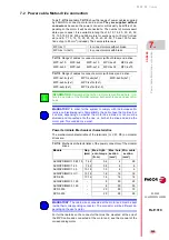
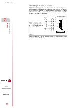
External absolute feedback
The attached figure shows the cable of the direct feedback supplied by
FAGOR to connect an external FAGOR absolute linear encoder) with si-
nusoidal signals (1 Vpp) and the drive. This cable
is supplied with con-
nectors at both ends
and
its sales reference is:
EC-
B-D cable
T. H7/13
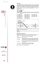
Range of EC-
PD cables. The number indicates their length in
meters including the connectors.
EC-1 PD
EC-3 PD
EC-6 PD
EC-9 PD
EC-12 PD
EC-2 PD
EC-4 PD
EC-8 PD
EC-10 PD
F. H7/2
Diagram of the direct feedback cable for an external FAGOR incremental
feedback (linear or rotary) sinusoidal (1 Vpp) or square-wave (differential
TTL).
T. H7/14
Range of EC-
B-D cables. The number indicates their length in
meters including the connectors.
EC-1B-D
EC-3B-D
EC-6B-D
EC-9B-D
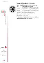
F. H7/3
Diagram of the direct feedback cable for the FAGOR absolute linear encod-
er.
Cable 4x2x0.14
Twisted pairs. Overall shield.
Overall shield connected to chassis pin
(on the sensor side and drive side)
6
11
2
9
Pin
I0
A
+5 V DC
Signal
(HD,
Sub-D,
M15)
Front view
to the drive - X3 -
GND
1
5
4
3
15
FAGOR
EC-X PD
sensor cable
Length in meters; including connectors
Chassis
To external incremental
feedback device
B
B
A
I0
1/2/3/4/6/8/9/10/12
Brown
White
Green
Yellow
Blue
Red
Grey
Pink
1
5
15
11
6
Cable 4x0.09+4x0.14+(4x0.09)
6
11
2
9
Pin
DATA
B
A
+5 V DC
Signal
(HD,
Sub-D,
M15)
Front view
GND
1
5
4
3
15
1/3/6/9
8
CLK
7
12
GND SENSE
+5 SENSE
10
A
B
DATA
CLK
1
5
15
11
6
Brown
White
Green
Yellow
Blue
Red
Grey
Pink
Black
Purple
Red-Blue
Grey-Pink
FAGOR
EC-XB-D
sensor cable
Length in meters; including connectors
To external absolute
feedback device
to the drive - X3 -
Twisted pairs. Overall shield.
Overall shield connected to chassis
(on the sensor side and drive side).
Summary of Contents for DDS
Page 1: ...DRIVE DDS Hardware manual Ref 1310...
Page 6: ...I 6 DDS HARDWARE Ref 1310...
Page 9: ......
Page 10: ......
Page 11: ......
Page 12: ......
Page 16: ...16 Ref 1310 DDS HARDWARE...
Page 30: ...1 DESCRIPTION 30 Description DDS HARDWARE Ref 1310...
Page 94: ...2 POWER SUPPLIES 94 Power supplies DDS HARDWARE Ref 1310...
Page 188: ...3 DRIVE MODULES 188 Drive modules DDS HARDWARE Ref 1310...
Page 204: ...4 AUXILIARY MODULES 204 Auxiliary modules DDS HARDWARE Ref 1310...
Page 232: ...SELECTING CRITERIA 5 232 Selection criteria DDS HARDWARE Ref 1310...
Page 266: ...7 CABLES 266 Cables DDS HARDWARE Ref 1310...
Page 312: ...8 INSTALLATION 312 Installation DDS HARDWARE Ref 1310...
Page 326: ...9 FUNCTIONAL SAFETY 326 Functional safety DDS HARDWARE Ref 1310...
Page 354: ...10 CONNECTION DIAGRAMS 354 Connection diagrams DDS HARDWARE Ref 1310...
Page 378: ...12 SALES REFERENCES 378 Sales references DDS HARDWARE Ref 1310...
Page 384: ...13 COMPATIBILITY 384 Compatibility DDS HARDWARE Ref 1310...
Page 385: ......

