background image


Updated 

on 

Update summary 

Updated 

version 


Version number: D3


Summary of Contents for EtherCAT CoolDrive RC Series

Page 1: ...Updated on Update summary Updated version Version number D3 ...

Page 2: ...ogy Beijing Co Ltd 2017 Tsino Dynatron Electrical Technology Beijing Co Ltd March 2017 CoolDrive RC Series Servo Drive User Manual EtherCAT is registered trademark and patented technology licensed by Beckhoff Automation GmbH Germany I ...

Page 3: ... specific conditions Tsino Dynatron does not guarantee that all given procedures and wirings are universal 3 Please contact us if the product is used for life related medical instruments public service facilities or facilities that may harm personal safety such as elevators passenger transport systems etc 4 Please contact us if the product is used for nuclear control aerospace equipment equipment ...

Page 4: ...hly Rotate the motor shaft by hand if it can run smoothly the servo motor shaft is working well for motors with electromagnetic brake the brake needs to be forced open Accessories Check the list shipped with the product to make sure you receive the right models and quantity of accessories If you have any questions please contact the agencies or our sales representatives Revisions Version No Releas...

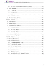
Page 5: ...ons 4 2 2 RC Series drive General Technical Specifications 4 2 2 1 RC Series Drive Specific Technical Specifications 6 2 2 2 Encoder Interface Technical Specifications 6 2 2 3 Mounting Dimensions 6 2 3 Dimension Drawing of RC2 6 2 3 1 Dimension Drawing of RC3 7 2 3 2 Dimension Drawing of RC4 8 2 3 3 Dimension Drawing of RC6 1 2 3 4 Chapter 3 Installation 2 Environmental Requirements 2 3 1 Mechanic...

Page 6: ...icator Status 30 4 2 2 Chapter 5 Trial Operation 31 Preparation Before Trial Operation 31 5 1 Precautions 31 5 1 1 Servo Parameter Settings 31 5 1 2 Trial Operation Through DriveStarter 32 5 2 Precautions 32 5 2 1 Trial Operation Under Point to Point PP Mode 33 5 2 2 Trial Operation Under Profile Velocity PV Mode 33 5 2 3 Trial Operation Under PT Mode 36 5 2 4 Chapter 6 Object Dictionary 39 Object...

Page 7: ... 78 6 4 5 Basic Adjustment Parameters 88 6 4 6 Filter Parameters 94 6 4 7 Limit Parameters 99 6 4 8 Monitor Parameters 101 6 4 9 Chapter 7 Running 106 Control Source Selection 106 7 1 Power Loop Setting 107 7 2 Motor Parameters 108 7 3 Encoder Setting 113 7 4 Braking 117 7 5 Regenerative braking 117 7 5 1 Motor brake activated 119 7 5 2 Modes of Operation 122 7 6 Basic Running Function Setting 123...

Page 8: ...n Output 145 7 8 7 Position Following Setting 146 7 8 8 Positioning Vibration Suppression Function 147 7 8 9 Position Unit Setting 149 7 8 10 Position Saved on Last Power Off 149 7 8 11 Servo ON Vibration Suppression 150 7 8 12 Software Position Limit Function 151 7 8 13 Velocity Control 152 7 9 CSV Mode Running 152 7 9 1 Basic Setting of Velocity Control 153 7 9 2 Square Wave Speed Setting 155 7 ...

Page 9: ...unction 178 7 10 8 Others 179 7 11 Inverter Rated Current 179 7 11 1 Encoder Resetting 179 7 11 2 Protection Thresholds for Over Current Over Voltage and Under Voltage 180 7 11 3 Charge Relay Control Function 181 7 11 4 Rotor Positioning Error Detection Sensitivity 181 7 11 5 Flux weaking control 181 7 11 6 Rotor Compensation Angle Detection 182 7 11 7 Alarm Operation Switch 185 7 11 8 Chapter 8 A...

Page 10: ...ts and Handling Suggestions 206 9 3 Unrecoverable Faults 206 9 3 1 Recoverable Faults 0 209 9 3 2 Recoverable Faults 1 214 9 3 3 Recoverable Faults 2 219 9 3 4 Alarm and Handling Suggestions 225 9 4 Chapter 10 Appendix 230 RC Series Parameter List 230 10 1 RC Series Object Dictionary 235 10 2 Communication parameter objects 235 10 2 1 CiA402 Standard Parameters 242 10 2 2 RC Series Parameter Objec...

Page 11: ... braking device should be applied upon motor braking failure Environmental Requirements 1 3 The transport storage installation and use of the drive must follow the instructions described in these manual as well as specific environmental requirements Operational Guidance 1 4 Personnel responsible for design installation and commissioning should follow all relevant regulations such as national wirin...

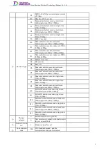
Page 12: ...5Arms 55 Shaft 1 has a rated output current of 5Arms and shaft 2 has a rated output current of 5Arms 02 Shaft 1 shaft 3 have a rated output current of 2 5Arms Only for RC6 model selection 05 Shaft 1 shaft 3 have a rated output current of 5Arms Rated output current of shaft group 2 00 Without shaft 3 and shaft 4 Only for RC2 RC3 and RC4 model selection 20 Shaft 3 has a rated output current of 2 5Ar...

Page 13: ...olute encoder multi turn 16Bit single turn 17Bit 2 5Mbps P2 Panasonic absolute encoder multi turn 16Bit single turn 20Bit 2 5Mbps P1 Panasonic absolute encoder single turn 17Bit 2 5Mbps P3 Panasonic absolute encoder single turn 20Bit 2 5Mbps P4 Panasonic absolute encoder multi turn 16Bit single turn 23Bit 2 5Mbps K0 SANKYO absolute encoder single turn 17Bit multi turn 24Bit 2 5Mbps K1 SANKYO absol...

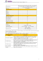
Page 14: ...t 2 channels Alarm output 1 channel max output current 0 1A Fan output 2 channels total max output current 0 4A Shaft control IO Only for S products High speed DI 2 channels Low speed DI 2 channels DO 1 channels Regenerative braking Braking resistor operation DC bus voltage DC 385V Min resistance of external braking resistor 65Ω Control performance Min control cycle of current loop 125us Min contr...

Page 15: ... represents standard features supported by the product represents optional features supported by the product Note 4 See the table below for the description of integrated security features Integrated security features Description STO Safe Torque Off Once this function is activated PWM output is blocked the motor output is stopped and the motor stops freely preventing the drive mechanism from restar...

Page 16: ...5 2 5 2 5 7 5 7 5 7 5 7 5 W251 H231 D82 W251 H231 D109 CDRC4 A5222 XXXX 5 2 5 2 5 2 5 15 7 5 7 5 7 5 CDRC4 A5552 XXXX 5 5 5 2 5 15 15 15 7 5 CDRC4 A5555 XXXX 5 5 5 5 15 15 15 15 CDRC6 A0202 XXXX 2 5 2 5 2 5 2 5 2 5 2 5 7 5 7 5 7 5 7 5 7 5 7 5 W315 H230 D76 W315 H230 D100 CDRC6 A0502 XXXX 5 5 5 2 5 2 5 2 5 15 15 15 7 5 7 5 7 5 CDRC6 A0505 XXXX 5 5 5 5 5 5 15 15 15 15 15 15 Encoder Interface Technic...

Page 17: ...Tsino Dynatron Electrical Technology Beijing Co Ltd Dimension Drawing of RC3 2 3 2 7 ...

Page 18: ...Tsino Dynatron Electrical Technology Beijing Co Ltd Dimension Drawing of RC4 2 3 3 8 ...

Page 19: ...Tsino Dynatron Electrical Technology Beijing Co Ltd 9 ...

Page 20: ...Tsino Dynatron Electrical Technology Beijing Co Ltd Dimension Drawing of RC6 2 3 4 1 ...

Page 21: ... finished product or system complies with all applicable laws and regulations of the country in which the drive is used Before installation please Make sure the product model is correct Check the product for any damage and make sure you have all accessories Check for any foreign matter inside the product and make sure the case screws are not loose Installation considerations Do not climb over the ...

Page 22: ...tructions Do not touch the internal components of the servo drive which may result in electric shock Check the voltage class of the servo drive carefully before power on failure to do so may lead to personal injury or equipment damage When the servo is powered up no one is allowed to enter the range of mechanical movement to prevent any possible personal injury The servo drive housing cannot be op...

Page 23: ...lation is reliable before power on otherwise it may damage the product When wiring the main circuit It is recommended to use the twisted pair wire or multi core twisted pair overall shielded wire for the input output signal line and encoder cable It is recommended that the length of the external IO signal line is no more than 3m and the encoder cable core and its length do not exceed the relevant ...

Page 24: ...trol system EtherCAT EtherCAT X4 J1 2 1 2 1 A B X22 X12 Shaft 1 shaft control I O Shaft 2 shaft control I O A B 5 1 A B 5 1 Note 1 Do not connect thepower supply to any other ports except port X1 which may damage the product 2 The input voltage of all ports should not exceed the allowed range 3 The output voltage of the motor brake port is DC24V and the maximum output current is 1A If its voltage ...

Page 25: ...ote2 J1 Encoder Shielded twisted pair wire Note1 J1 Encoder A1 A2 B1 B2 DATA Note2 DATA Note2 X4 J1 A B 2 1 Figure 3 4 2 RC2 Encoder Port X4 Wiring Diagram 3 4 1 3 RC2 Module Control I O Port X7 Wiring Diagram STO1 B5 A4 A5 24VGND B4 STO2 24VGND A1 24VGND 24V_OUT 24V_OUT STO internal 24V power supply X7 B3 24VGND ALM A1 A2 A3 A4 A5 B1 B2 B3 B4 B5 A3 24V_OUT B2 A2 FAN Fan optional 24VGND B1 FAN N24...

Page 26: ...onnect the BK and BK to the corresponding motor brakes separately 3 Makesure the wiring sequence is correct the connection is secure and the insulation is reliablebefore power on otherwise it may damage the product X3 A1 A2 A3 B1 B2 B3 A2 B2 A3 B3 BK BK A B 1 3 M Motor brake M Motor brake 24V BK 24V BK X3 A1 A2 A3 B1 B2 B3 A2 B2 A3 B3 BK BK A B 1 3 M Motor brake 24VDC KM M Motor brake 24VDC KM J2 ...

Page 27: ...3 B4 B5 A3 A2 A1 Homing switch Negative limit switch Positivelimit switch 24VGND 24VGND 24VGND 24VGND DO A B 1 5 HDI2 DO Touch Probe 1 Reserved Reserved X12 X22 Figure 3 4 5 RC2 Shaft Module I O Port X12 X22 Wiring Diagram Note 1 The RC2 system wiring diagram mentioned above is a RC2 universal servo product system wiring diagram while robot dedicated servo products have no shaft control I O 8 ...

Page 28: ...g resistor Resistance 65Ω Upper control system EtherCAT EtherCAT X4 J1 X5 J3 A B 2 1 2 1 2 1 A B X32 X12 X22 Shaft 2 shaft control I O Shaft 1 shaft control I O Shaft 3 shaft control I O A B 5 1 A B 5 1 A B 5 1 Note 1 Do not connect thepower supply to any other ports except port X1 which may damage the product 2 The input voltage of all ports should not exceed the allowed range 3 The output voltag...

Page 29: ... corresponding encoder side signals X4 J2 A B 2 1 1EVCC 1DATA 1DATA 1GND B2 A2 A1 B1 VCC Note2 GND Note2 J1 Encoder Shielded twisted pair wire Note1 J1 Encoder A1 A2 B1 B2 DATA Note2 DATA Note2 X4 J1 A B 2 1 Nikon Tamagawa Panasonic SANKYO MotorPower Vcc 5V Vcc E5V Vcc DC 5V GND 0V GND E0V GND GND DATA ES SD PS D DATA DATA ES SD PS D DATA Drive side signals Encoder side signals Note 1 The encoder ...

Page 30: ... Port X3 and X6 Wiring Diagram 24V BK J2 24V BK J1 J3 Note 1 The maximum output current of the motor brake terminal is 1A If the current carried by the motor brake exceeds the allowed range it must be controlled by an external relay 2 Do not short connect the BK end of each shaft which may incurdanger It is recommended to connect the BK and BK to the corresponding motorbrakes separately 3 Make sur...

Page 31: ... B5 A3 A2 A1 Homing switch Negative limit switch Positivelimit switch 24VGND 24VGND 24VGND 24VGND DO A B 1 5 HDI2 DO Touch Probe 1 Reserved Reserved X12 X22 X32 Figure 3 4 10 RC3 Shaft Control I O Port X12 X22 X32 Wiring Diagram Note 1 The RC3 system wiring diagram mentioned above is a RC3 universal servo product system wiring diagram while robot dedicated servo products have no shaft control I O ...

Page 32: ...mmunication debugging port Braking resistor Resistance 65Ω Upper control system EtherCAT EtherCAT X4 J1 X5 J3 A B 2 1 2 1 2 1 2 1 A B X32 X42 X12 X22 Shaft 2 shaft control I O Shaft 1 shaft control I O Shaft 3 shaft control I O Shaft 4 shaft control I O A B 5 1 A B 5 1 A B 5 1 A B 5 1 Note 1 Do not connect the power supply to any other ports except port X1 which may damage the product 2 The input ...

Page 33: ...2 A1 B1 VCC Note2 GND Note2 J1 Encoder Shielded twisted pair wire Note1 J1 Encoder A1 A2 B1 B2 DATA Note2 DATA Note2 X4 J1 A B 2 1 Nikon Tamagawa Panasonic SANKYO MotorPower Vcc 5V Vcc E5V Vcc DC 5V GND 0V GND E0V GND GND DATA ES SD PS D DATA DATA ES SD PS D DATA Drive side signals Encoder side signals Note 1 The encoder cable shielded wire isconnected to the cable bracket 2 See thetablebelow for ...

Page 34: ...ort X3 and X6 Wiring Diagram 24V BK J2 J4 24V BK J1 J3 Note 1 The maximum output current of the motor brake terminal is 1A If the current carried by the motor brake exceedsthe allowed range it must be controlled by an external relay 2 Do not short connect the BK end of each shaft which may incur danger It isrecommended to connect the BK and BK to the corresponding motor brakes separately 3 Makesur...

Page 35: ...GND HDI1 DI1 DI2 B3 B4 GND GND GND GND B1 B2 B5 A5 24V A4 A1 A2 A3 A4 A5 B1 B2 B3 B4 B5 A3 A2 A1 Homing switch Negative limit switch Positivelimit switch 24VGND 24VGND 24VGND 24VGND DO A B 1 5 HDI2 DO Touch Probe 1 Reserved Reserved X12 X22 X32 X42 Figure 3 4 15 RC4 Shaft Control I O Port X12 X22 X32 X42 Wiring Diagram 16 ...

Page 36: ...current is 1A If its voltage is not DC24V or the current carried by the motorbrake exceeds 1A it must be controlled by an externalrelay 4 Do not short connect the BK end of each shaft which may incurdanger It is recommended to connect the BK and BK to the corresponding motor brakes separately 5 Make sure the wiring sequence is correct the connection is secure and the insulation is reliable beforep...

Page 37: ...te2 AND Note2 Shaft 3 encoder Shielded twisted pair wire Note1 Shaft 3 encoder A1 A2 1 2 DATA Note2 DATA Note2 X4 T3 A 2 1 Nikon Tamagawa Panasonic SANKYO MotorPower Vcc 5V Vcc E5V Vcc DC 5V GND 0V GND E0V GND GND DATA ES SD PS D DATA DATA ES SD PS D DATA Drive side signals Encoder side signals Note 1 The encoder cable shielded wire isconnected to the cable bracket 2 See thetablebelow for correspo...

Page 38: ...K J2 J5 24V BK J1 J4 Note 1 The maximum output current of the motor brake terminal is 1A If the current carried by the motor brake exceedsthe allowed range it must be controlled by an external relay 2 Do not short connect the BK end of each shaft which may incur danger It isrecommended to connect the BK and BK to the corresponding motor brakes separately 3 Makesure the wiring sequence is correct t...

Page 39: ...ed Figure 3 4 20 RC6 Shaft Control I O Port X12 X22 X32 X42 X52 X62 Wiring Diagram Note 1 The RC6 system wiring diagram mentioned above is a RC6 universal servo product system wiring diagram while robot dedicated servo products have no shaft control I O Connector Pin Definition 3 4 5 3 4 5 1 RC2 Connector Pin Definition Control power input terminal connector X2 COM 24V 2 1 Pin number Pin Definitio...

Page 40: ...ake positive pole and negative pole short circuit can damage the drive In case of abnormal power on if there is any short circuit please disconnect the power supply immediately and contact Tsino Dynatron technical support B1 NC Reserved A2 BK Positive output of motor brake J2 B2 BK Negative output of motor brake J2 A3 BK Positive output of motor brake J1 B3 BK Negative output of motor brake J1 Enc...

Page 41: ...nd data 3 DP_PHY0_ RX Receive data 4 5 6 DP_PHY0_ RX Receive data 7 8 Serial port debugging terminal connector X10 Pin number Pin Definition Description Technical parameters 1 NC Suspended and unconnected 2 RS485 RS485 signal 3 RS485 RS485 signal 4 NC Suspended and unconnected 5 NC Suspended and unconnected 6 GND Signal ground 3 4 5 2 RC3 Connector Pin Definition Control power input terminal conne...

Page 42: ...e J2 B2 BK Negative output of motor brake J2 A3 BK Positive output of motor brake J1 J3 B3 BK Negative output of motor brake J1 J3 Encoder terminal connector X4 2 1 2 1 A B Shaft Pin number Pin Definition Description Technical parameters X4 J2 A1 DATA J2 encoder signal B1 DATA A2 GND J2 encoder power supply B2 VCC X4 J1 A1 DATA J1 encoder signal B1 DATA A2 GND J1 encoder power supply B2 VCC Encode...

Page 43: ...Send data 3 DP_PHY0_ RX Receive data 4 5 6 DP_PHY0_ RX Receive data 7 8 Serial port debugging terminal connector X10 Pin number Pin Definition Description Technical parameters 1 NC Suspended and unconnected 2 RS485 RS485 signal 3 RS485 RS485 signal 4 NC Suspended and unconnected 5 NC Suspended and unconnected 6 GND Signal ground 3 4 5 3 RC4 Connector Pin Definition Control power input terminal con...

Page 44: ...tput of motor brake J1 J3 Encoder terminal connector X4 X5 2 1 2 1 A B Shaft Pin number Pin Definition Description Technical parameters X4 J2 J5 J4 A1 DATA J2 J4 encoder signal B1 DATA A2 GND J2 J4 encoder power supply B2 VCC X4 J1 X5 J3 A1 DATA J1 J3 encoder signal B1 DATA A2 GND J1 J3 encoder power supply B2 VCC Module control I O terminal connector X7 A B 5 1 Pin number Pin Definition Descripti...

Page 45: ...1 24V Control power input positive pole Input voltage DC 24V 15 20 Input current without motor brake DC 2A 2 COM Control power input negative pole Power supply input terminal connector X1 R S T PE B P 5 6 4 3 2 1 Pin number Pin Definition Description Technical parameters 1 PE Protective ground Input voltage 220V 3AC 15 220V 1AC 15 Rated input current 12Arms 2 R Power supply R 3 S Power supply S 4 ...

Page 46: ...control I O terminal connector X7 A B 5 1 Pin number Pin Definition Description Technical parameters A1 24VGND 24V negative pole A2 24VGND 24V negative pole A3 24V_OUT Drive output 24V positive pole A4 24V_OUT Drive output 24V positive pole A5 24V_OUT Drive output 24V positive pole B1 FAN Fan B2 FAN Fan B3 ALM Alarm output B4 STO2 STO2 B5 STO1 STO1 Shaft control I O terminal connector X12 X22 X32 ...

Page 47: ...correct and reliable and the cored wire is firmly clamped 6 Make sure the cables are wired uncrossed with allowance at the turning points away from sharp parts of the machine and free from extrusion 7 Make sure both ends of the cable are identified properly clearly and neatly 8 The dynamic line and ground wire should be made of a whole piece of copper core without joint and cable sheath damage 9 M...

Page 48: ... 1 2 Wiring requirements Number Inspection item 1 Make sure the power cable and ground wire outside the cabinet are routed straightly strapped separately with other cables and away from sharp parts of the machine 2 The excess part of the ground wire and power cable should be cut off rather than coiled 3 No cable should be overlapped on heating objects such as radiator braking resistors etc 4 The c...

Page 49: ...abled state with warnings Flash red quickly It is in fault state and the fault cannot be reset Flash red slowly It is in fault state and the fault can be reset EACT STA Indication OFF Initializing the communication network Flash The communication network is in pre running state Sparkle The communication network is in safe operation state Constant ON The communication network is in running state No...

Page 50: ...check the oil seal part for any damage Make sure the engine oil has been applied For servo motors after long term preservation please inspect them before trial operation 5 1 1 2 Condition of Servo Drive Make sure the servo drive s control power voltage and power supply voltage are normal Make sure the power cable encoder cable brake cable and I O cable are properly connected Servo Parameter Settin...

Page 51: ...or each motor shaft before trial operation Enter the value directly if it is already known or detect it through the following method if it is unknown If the motor is not mounted to the mechanical equipment e g not mounted to the robot body you can detect it with conventional detection method If the motor is already mounted to the mechanical equipment e g mounted to the robot body please detect it ...

Page 52: ...0E Manual Step Target Position 0x210F Manual Step Profile Velocity 0x2110 Manual Step End Velocity 0x2111 Manual Step Profile Acceleration 0x2112 Manual Step Profile Deceleration Trial Operation Under Profile Velocity PV Mode 5 2 3 So far there are four ways of PV mode trial operation of DriveStarter host commissioning software including Simple Jogging TTV1 Programming Jogging 1 TTV2 Programming J...

Page 53: ...Tsino Dynatron Electrical Technology Beijing Co Ltd 5 2 3 1 Diagram of Trial Operation Under PV Mode Figure 5 2 2 Diagram of Simple Jogging TTV1 Figure 5 2 3 Diagram of Programming Jogging 1 TTV2 34 ...

Page 54: ...Tsino Dynatron Electrical Technology Beijing Co Ltd Figure 5 2 4 Diagram of Programming Jogging 2 TTV3 Figure 5 2 5 Diagram of Sinusoidal Jogging STV 35 ...

Page 55: ... Pulse Wait Time 0x2102 Program Pulse UpTime 0x2103 Program Pulse Down Time 0x2104 Program Pulse Duration Time 0x2105 Program Pulse Loop Count 0x2106 Program Sin Peak Speed 0x2107 Program Sin Offset Speed 0x2108 Program Sin frequency Trial Operation Under PT Mode 5 2 4 So far there are four ways of PT mode trial operation of DriveStarter host commissioning software including Simple Torque Profile ...

Page 56: ...Tsino Dynatron Electrical Technology Beijing Co Ltd Figure 5 2 7 Diagram of Programming Torque Profile 1 TTT2 Figure 5 2 8 Diagram of Programming Torque Profile 2 TTT3 37 ...

Page 57: ...rofile 1 TTT2 0x8002 Programming Torque Profile 2 TTT3 0x8003 Sine torque test mode STT 0x8004 Rotor position compensation angle test mode RCT 0x8005 0xFFFF Reserved manufacturer specific 0x2113 Program Pulse Torque 0x6087 Torque Slope 0x2101 Program Pulse Wait Time 0x2102 Program Pulse UpTime 0x2103 Program Pulse Down Time 0x2104 Program Pulse Duration Time 0x2105 Program Pulse Loop Count 0x2109 ...

Page 58: ...data type information such as INT16 Dir Object operation attributes Ro Read only RW Read and Write Object Type Object data type VAR Variable ARRAY array RECORD record PDO Mapping Mapping of PDO objects NO Mapping not supported RXPDO Data receiving mapping TXPDO Data sending mapping RXPDO TXPDO Data receiving sending mapping Communication parameter objects 6 2 Devices Description 6 2 1 0x1000 Devic...

Page 59: ...T32 Object mapped in the 2nd The default object is 0x607A 0x03 NO rw UINT32 Object mapped in the 3rd The default object is 0x60FF 0x04 NO rw UINT32 Object mapped in the 4th The default object is 0x6071 0x05 NO rw UINT32 Object mapped in the 5th The default object is 0x6060 0x06 NO rw UINT32 Object mapped in the 6th The default object is 0x5FFF 0x07 NO rw UINT32 Object mapped in the 7th The default...

Page 60: ...NO rw UINT32 Object mapped in the 10th 0x1603 4th Reception PDO Index 0x1603 Object type REC Name 4th Reception PDO Sub index PDO mapping Read and write operations Data type Unit Description 0x00 NO rw UINT8 Number of Entry to RxPDO 0x01 NO rw UINT32 Object mapped in the 1st The default object is 0x6040 0x02 NO rw UINT32 Object mapped in the 2nd The default object is 0x6071 0x03 NO rw UINT32 Objec...

Page 61: ...UINT32 Object mapped in the 8th The default object is 0x60FD 0x09 NO rw UINT32 Object mapped in the 9th The default object is 0x60B9 0x0A NO rw UINT32 Object mapped in the 10th The default object is 0x60BA 0x1A01 2nd Transmission PDO Index 0x1A01 Object type REC Name 2nd Transmission PDO Sub index PDO mapping Read and write operations Data type Unit Description 0x00 NO rw UINT8 Number of Entry to ...

Page 62: ... in the 8th Reserved 0x09 NO rw UINT32 Object mapped in the 9th Reserved 0x0A NO rw UINT32 Object mapped in the 10th Reserved 0x1A03 4th Transmission PDO Index 0x1A03 Object type REC Name 4th Transmission PDO Sub index PDO mapping Read and write operations Data type Unit Description 0x00 NO rw UINT8 Number of Entry to TxPDO 0x01 NO rw UINT32 Object mapped in the 1st The default object is 0x6041 0x...

Page 63: ...T16 SubIndex004 0x1C32 Output Sync Manager Parameter Index 0x1C32 Object type RECORD Name Output Sync Manager Parameter Sub index PDO mapping Read and write operations Data type Unit Description 0x00 NO rw UINT8 Number of Entries 0x01 NO r UINT16 Synchronization Type 0x00 Free Run not synchronized 0x01 Synchronized with SM Event 0x02 DC Sync0 synchronized with Sync0 Event 0x03 DC Sync1 synchronize...

Page 64: ...ift Time Time between Sync0 event and the Inputs Latch 0x04 NO rw UINT16 ns Sync Modes Supported Bit0 Free Run Supported Bit1 Synchronous Supported Bit4 2 DC Type Supported 000 No DC 001 DC Sync0 010 DC Sync1 Bit6 5 Shift Settings 00 No Input Shift Supported 01 Input Shift with Local Timer 10 Input Shift with S 0x05 NO rw UINT32 Minimum Cycle Time Same time as for 0x1C32 05 See Figure 7 2 1 0x06 N...

Page 65: ... Cycle Time 0x1C32 02 SYNC0 Event SYNC0 Event Calc and Copy time 0x1C32 06 Minimum Cycle Time 0x1C32 05 Output Valid Input Latch Calc and Copy time 0x1C32 06 Delay Time 0x1C32 09 Delay Time 0x1C32 09 Figure 6 2 1 DC mode communication timing diagram CiA402 Parameter Objects 6 3 System State Machine 6 3 1 6 3 1 1 System State Machine Figure 7 3 1 System state machine diagram 46 ...

Page 66: ...and Disconnect the pre charge relay switch 7 Received Quick Stop or Disable voltage command None 8 Received Shutdown command and 0x605B 0 Disable motor output and disconnect the pre charge relay switch 8 Received Shutdown command and 0x605B 1 Select the controlled stop mode and execute 8 Controlled stop completed Disable motor output and disconnect the pre charge relay switch 9 Received Disable vo...

Page 67: ...apping Read and write operations Data type Unit Description 0x00 RXPDO rw UINT16 Control word The control word shows the control commands of the drive system state machine and each bit indicates a different meaning Bit0 Pre charge relay closed Bit1 Main power on Bit2 Quick stop Bit3 Operation enabled Bit4 Bit6 Operation method definition Bit7 Fault reset Bit8 Stop Bit9 Bit10 Reserved Bit11 Manufac...

Page 68: ... limit flag bit 1 limits in instruction 0 no limit in instruction Bit12 Bit13 are depending on the current mode see Table 7 3 2 Bit14 Motor rotation flag bit 1 motor is rotating 0 motor is at rest Bit15 Reserved Table 7 3 2 Meanings of Bit12 and Bit13 under different control modes CSP mode Bit13 Position tracking error bit 1 Position following error occurred 0 No position following error Bit12 Pos...

Page 69: ...n Disabled state 0x02 Emergency stop deceleration decelerates to zero and the enters Switch on Disabled state 0x605B Shutdown option code Index 0x605B Object type VAR Name Shutdown option code Sub index PDO mapping Read and write operations Data type Unit Description 0x00 NO rw INT16 Shutdown option code 0x00 Immediately stop the motor output and the motor stops freely 0x01 Slope deceleration dece...

Page 70: ...ode PT 0x05 Reserved 0x06 Homing mode HM 0x07 Interpolation position mode IP not supported yet 0x08 Cyclic Synchronous Position mode CSP 0x09 Cyclic synchronous velocity mode CSV 0x0A Cyclic synchronous torque mode CST Byte1 Reserved Byte2 Power on default control modes of operation 0x01 Profile position mode PP 0x02 Velocity mode VL 0x03 Profile velocity mode PV 0x04 Profile torque mode PT 0x05 R...

Page 71: ...ue 0x6063 Position actual internal value Index 0x6063 Object type VAR Name Position actual internal value Sub index PDO mapping Read and write operations Data type Unit Description 0x00 TXPDO ro INT32 Inc Actual internal position value not supported yet 0x6064 Position actual value Index 0x6064 Object type VAR Name Position actual value Sub index PDO mapping Read and write operations Data type Uni...

Page 72: ...16 ms Position window time Set the position window time 0x607A Target position Index 0x607A Object type VAR Name Target position Sub index PDO mapping Read and write operations Data type Unit Description 0x00 RXPDO rw UINT32 inc Target position The position command value planned and sent by the motion controller to the drive 0x607E Polarity Index 0x607E Object type VAR Name Polarity Sub index PDO ...

Page 73: ...ex 0x6084 Object type VAR Name Profile deceleration Sub index PDO mapping Read and write operations Data type Unit Description 0x00 RXPDO rw UINT32 inc s 2 Profile deceleration 0x6085 Quick stop deceleration Index 0x6085 Object type VAR Name Emergency stop deceleration Sub index PDO mapping Read and write operations Data type Unit Description 0x00 RXPDO rw UINT32 inc ms Emergency stop deceleration...

Page 74: ...60C5 Max acceleration Index 0x60C5 Object type VAR Name Max acceleration Sub index PDO mapping Read and write operations Data type Unit Description 0x00 RXPDO rw UINT32 inc ms Max acceleration 0x60C6 Max deceleration Index 0x60C6 Object type VAR Name Max deceleration Sub index PDO mapping Read and write operations Data type Unit Description 0x00 RXPDO rw UINT32 inc ms Max deceleration 0x60F4 Follo...

Page 75: ... and write operations Data type Unit Description 0x00 TXPDO ro INT32 inc s Velocity demand value Provides the velocity demand value from the trajectory generator x606C Velocity actual value Index 0x606C Object type VAR Name Velocity actual value Sub index PDO mapping Read and write operations Data type Unit Description 0x00 TXPDO ro INT32 inc s Actual velocity value Provides the actual velocity va...

Page 76: ...aximum profile velocity 0x60C2 Interpolation time period Index 0x60C2 Object type REC Name Interpolation time period Sub index PDO mapping Read and write operations Data type Unit Description 0x00 NO rw UINT8 Number of Entries 0x01 RXPDO rw UINT8 Ip time units 0x02 RXPDO rw UINT8 Ip time index 0x60FF Target velocity Index 0x60FF Object type VAR Name Target velocity Sub index PDO mapping Read and w...

Page 77: ... Provides the torque command value from the trajectory generator 0x6075 Motor rated current Index 0x6075 Object type VAR Name Motor rated current Sub index PDO mapping Read and write operations Data type Unit Description 0x00 NO rw UINT32 mA Motor rated current Set the motor rated current This parameter is provided by the manufacturer 0x6076 Motor rated torque Index 0x6076 Object type VAR Name Mot...

Page 78: ... The DC bus voltage observation which is the same with the actual drive instantaneous DC bus voltage 0x6087 Torque slope Index 0x6087 Object type VAR Name Torque slope Sub index PDO mapping Read and write operations Data type Unit Description 0x00 RXPDO rw UINT32 s Torque slope Set the torque changing rate 0x6088 Torque profile type Index 0x6088 Object type VAR Name Torque profile type Sub index P...

Page 79: ...Homing for object 0x6060 0x607C Home offset Index 0x607C Object type VAR Name Home offset Sub index PDO mapping Read and write operations Data type Unit Description 0x00 NO rw INT32 inc Home offset The offset values of zero point and mechanical home Once the home is set the absolute position of the subsequent motion is the position value relative to the home offset The zero point offset is shown b...

Page 80: ...2 0x13 No index pulse homing 3 0x14 No index pulse homing 4 0x15 No index pulse homing 5 0x16 No index pulse homing 6 0x17 No index pulse homing 7 0x18 No index pulse homing 8 0x19 No index pulse homing 9 0x1A No index pulse homing 10 0x1B No index pulse homing 11 0x1C No index pulse homing 12 0x1D No index pulse homing 13 0x1E No index pulse homing 14 0x1F 0x20 Reserved 0x21 Index pulse homing 1 ...

Page 81: ...pe Unit Description 0x00 RXPDO rw UINT16 TP control word 0x60B9 Touch probe status Index 0x60B8 Object type VAR Name Touch probe status Sub index PDO mapping Read and write operations Data type Unit Description 0x00 TXPDO ro UINT16 TP control word 0x60BA Touch probe pos 1 pos value Index 0x60BA Object type VAR Name Touch probe pos 1 pos value Sub index PDO mapping Read and write operations Data ty...

Page 82: ... Non standard motor 0x01 0x02 Reserved 0x03 Permanent magnet synchronous motor 0x04 0x05 Reserved 0x06 Winding asynchronous motor 0x07 Squirrel cage asynchronous motor 0x08 0x09 Reserved 0x0A Sine wave brushless DC motor 0x0B Trapezoidal wave brushless DC motor Byte1 Reserved 0x6502 Supported drive modes Index 0x6502 Object type VAR Name Supported drive modes Sub index PDO mapping Read and write o...

Page 83: ...ization may fail reporting fault Initializing PWM application The specific models are as follows 0x00 CDRC 002 0x01 CDRC 003 0x02 CDRC 005 0x02 CDRC 008 Byte3 reserved the default is 0 0x2034 Regenerative Resistor Capacity Index 0x2034 Object type VAR Name Regenerative Resistor Capacity Sub index PDO mapping Read and write operations Data type Unit Description 0x00 NO rw UINT16 Watt Regenerative R...

Page 84: ...regenerative braking resistor 0x2038 Clear error history Index 0x2038 Object type VAR Name Clear error history Sub index PDO mapping Read and write operations Data type Unit Description 0x00 RXPDO rw UINT16 Clear Error History Clear the error history 0x2039 Error history Index 0x2039 Object type REC Name Error history Sub index PDO mapping Read and write operations Data type Unit Description 0x00 ...

Page 85: ...ly read the drive status 2 Byte3 Commissioning without motor is used for debugging without motor If Byte3 is set to 0x01 commissioning without motor and encoder is possible If byte3 is set to 0x02 commissioning without motor for real encoder is possible The default value is 0x00 0x204A Over current protection threshold value Index 0x204A Object type VAR Name Over current protection threshold value...

Page 86: ... higher than this value is a necessary condition for enabling the drive This parameter is set by the manufacturer and can not be modified 0x2085 Brake Chopper switched on Voltage Index 0x2085 Object type VAR Name Brake Chopper switched on Voltage Sub index PDO mapping Read and write operations Data type Unit Description 0x00 NO ro UINT32 mV Brake Chopper switched on Voltage of the drive When the d...

Page 87: ...Position Compensation Angle Sub index PDO mapping Read and write operations Data type Unit Description 0x00 NO rw UINT32 0 001 rad Motor Rotor Position Compensation Angle The motor rotor position compensation angle is the physical offset angle when the motor encoder is installed Refer to Chapter 5 1 2 5 for the detection and setting method of this parameter 0x202D Motor Overload Alarm Level Index ...

Page 88: ... of the motor 0x00 Level 0 0x01 Level 1 0x02 Level 2 0x03 Level 3 0x04 Level 4 0x05 Level 5 0x06 Level 6 0x20A6 Motor Overload Warning Level Index 0x20A6 Object type VAR Name Motor Overload Warning Level Sub index PDO mapping Read and write operations Data type Unit Description 0x00 NO rw UINT16 Motor Overload Warning Threshold When the motor load is over the set value the drive alarms The STA ind...

Page 89: ...n 0x00 NO rw UINT32 mΩ Winding Resistance Set the motor winding resistance This parameter is provided by the manufacturer 0x20C4 Winding Inductance Index 0x20C4 Object type VAR Name Winding Inductance Sub index PDO mapping Read and write operations Data type Unit Description 0x00 NO rw UINT32 mH Winding Inductance Set the motor winding inductance This parameter is provided by the manufacturer 0x20...

Page 90: ...ct type VAR Name Motor Thermal Time Constant Sub index PDO mapping Read and write operations Data type Unit Description 0x00 NO rw UINT16 Sec Motor thermal time constant Set the motor thermal time constant This parameter is provided by the manufacturer 0x20CA Flux Weaking Compensation Threshold Velocity Index 0x20CA Object type VAR Name Flux Weaking Compensation Threshold Velocity Sub index PDO ma...

Page 91: ...00 Disable the encoder battery low voltage detection 0x01 Detect the encoder battery low voltage as a warning 0x02 Detect the encoder battery low voltage as a fault 0x200A Supported Encoder Type Index 0x200A Object type VAR Name Supported Encoder Type Sub index PDO mapping Read and write operations Data type Unit Description 0x00 TXPDO ro INT16 Supported Encoder Types Provides the supported encode...

Page 92: ... Encoder Multi turn upper limit resolution is equal to 7 0x08 Interface Encoder Multi turn upper limit resolution is equal to 8 0x09 Interface Encoder Multi turn upper limit resolution is equal to 9 0x0A Interface Encoder Multi turn upper limit resolution is equal to 10 0x0B Interface Encoder Multi turn upper limit resolution is equal to 11 0x0C Interface Encoder Multi turn upper limit resolution ...

Page 93: ... turn Resolution Set the absolute encoder single turn resolution based on the actual motor encoder single turn value in real application 0x2077 Absolute Encoder Multi turn Resolution Index 0x2077 Object type VAR Name Absolute Encoder Multi turn Resolution Sub index PDO mapping Read and write operations Data type Unit Description 0x00 NO rw UINT16 inc rev Absolute encoder multi turn bits Set the ab...

Page 94: ...mapping Read and write operations Data type Unit Description 0x00 NO rw UINT16 r min Motor Brake Active Speed Threshold Value Valid when 0x293C Byte3 0x00 When the motor s actual speed is lower than the set value the motor brake is active 0x2067 Motor Brake Release OK Delay Time Index 0x2067 Object type VAR Name Motor Brake Active Speed Threshold Value Sub index PDO mapping Read and write operatio...

Page 95: ...braking action The target values from upper control system is valid 0x6041 12 Motor speed 0msec min 3sec Drive enabled DC voltage threshold 0x204D No56 Control power closed Power supply closed 0 1 0 Servo disabled 1 Servo enabled Motor brake activated Motor brake released 0 Motor is not exciting 1 Motor is working 0 The host computer command is invalid 1 The target values from upper control system...

Page 96: ...ted Control power disconnected 0msec min 1 Servo disabling process control word 0x6040 3 0 0x0F 0x07 and slopedecelerates to zero delay to stop the motor output 0x605C 9 No111 or control word 0x6040 3 0 0x0F 0x06 and slopedecelerates to zero delay to stop the motor output 0x605B 9 No110 TASADLY TASADLY Active Stop Delay Time 0x2092 No79 TMBAHDLY TMBAHDLY Motor Brake Active Holding Delay Time 0x203...

Page 97: ...ction switch of position following error 0x00 Disable detection of position following error 0x01 Enable detection of position following error 0x2001 Position Disturbance Compensation Gain Index 0x2001 Object type VAR Name Position Disturbance Compensation Gain Sub index PDO mapping Read and write operations Data type Unit Description 0x00 NO rw UINT32 Position Disturbance Compensation Gain Positio...

Page 98: ...equency Index 0x2018 Object type VAR Name Disturbance Torque Compensation Lowpass Filter Cutoff Frequency Sub index PDO mapping Read and write operations Data type Unit Description 0x00 NO rw UINT32 Hz Disturbance Torque Compensation Lowpass Filter Cutoff Frequency System oscillation can be caused due to inappropriately set of this parameter therefore it should be set carefully The higher the para...

Page 99: ...ame Position control cycle time selection Sub index PDO mapping Read and write operations Data type Unit Description 0x00 NO rw UINT16 Position control cycle time selection Set the position control cycle time and set the unit to a multiple of the velocity loop control cycle 0x2032 Velocity control cycle time selection Index 0x2032 Object type VAR Name Velocity control cycle time selection Sub inde...

Page 100: ...urrent regulator adaptive control and enable velocity regulator adaptive control 0x2080 Velocity Profile Type Index 0x2080 Object type VAR Name Velocity Profile Type Sub index PDO mapping Read and write operations Data type Unit Description 0x00 NO rw UINT32 Velocity Profile Type Byte0 Velocity Profile Type 0x00 TTV0 0x01 Simple jogging TTV1 0x02 Programming jogging TTV2 0x03 Programming jogging T...

Page 101: ...he motor output and the motor stops freely 0x01 Slope deceleration decelerates to zero and then stop the motor output 0x02 Emergency stop deceleration decelerates to zero and then stop the motor output Byte3 Reserved The default value is 0 0x2094 Fault Operation Switch Index 0x2094 Object type VAR Name Fault Reaction Stop Option 2 Sub index PDO mapping Read and write operations Data type Unit Desc...

Page 102: ...owing window 0x20A4 Velocity following window time Index 0x20A4 Object type VAR Name Velocity following window time Sub index PDO mapping Read and write operations Data type Unit Description 0x00 NO rw UINT16 ms Velocity following window time Set the velocity following window time 0x20D1 Rotor Compensation Angle Detection Setting Index 0x20D1 Object type VAR Name Rotor Compensation Angle Detection...

Page 103: ...nit Description 0x00 NO rw UINT16 r min Set Speed of Square Wave In velocity profile PV TTV2 PV TTV3 mode set the square wave speed 0x2101 Program Pulse Wait Time Index 0x2101 Object type VAR Name Program Pulse Wait Time Sub index PDO mapping Read and write operations Data type Unit Description 0x00 NO rw UINT16 ms Square Wave Speed Wait Time In velocity profile PV TTV2 PV TTV3 mode set the square...

Page 104: ...cription 0x00 NO rw UINT16 ms Square Wave Speed Duration Time In velocity profile PV TTV2 PV TTV3 mode set the square wave speed duration time 0x2105 Program Pulse Repeat Count Index 0x2105 Object type VAR Name Program Pulse Repeat Count Sub index PDO mapping Read and write operations Data type Unit Description 0x00 NO rw UINT16 Square Wave Speed Repeat Count In velocity profile PV TTV2 PV TTV3 mo...

Page 105: ...e Wave Speed Frequency In velocity profile PV STV mode set the sine wave speed frequency 0x2109 Program Sin Peak Torque Index 0x2109 Object type VAR Name Program Sin Peak Torque Sub index PDO mapping Read and write operations Data type Unit Description 0x00 NO rw UINT16 Sine Wave Peak Torque In velocity profile PT STT mode set the sine wave peak torque and the unit is permillage of rated torque 0x...

Page 106: ...ame Jog Acceleration Time Sub index PDO mapping Read and write operations Data type Unit Description 0x00 NO rw UINT32 ms Manual Jog Acceleration Time Acceleration timein velocity profile PV TTV1 mode which is the same with the deceleration time 0x210E Manual Step Target Position Index 0x210E Object type VAR Name Manual Step Target Position Sub index PDO mapping Read and write operations Data type...

Page 107: ...bject type VAR Name Manual Step Profile Deceleration Sub index PDO mapping Read and write operations Data type Unit Description 0x00 NO rw UINT32 inc ms Manual Step Profile Deceleration Set the manual step profile deceleration in PP mode 0x2113 Program Pulse Torque Index 0x2113 Object type VAR Name Program Pulse Torque Sub index PDO mapping Read and write operations Data type Unit Description 0x00...

Page 108: ...y feedforward gain can improve the position following error but a too high value may cause mechanical vibration 0x2042 Position Control Gain2 Index 0x2042 Object type VAR Name Position Control Gain2 Sub index PDO mapping Read and write operations Data type Unit Description 0x00 RXPDO rw UINT32 Position Loop Proportional Gain2 This parameter is valid when parameter 0x2040 is set to 0 The greater th...

Page 109: ...gration time can reduce the overshoot during acceleration deceleration but a too high value may slow down the system response 0x2046Velocity Control Gain2 Index 0x2046 Object type VAR Name Velocity Control Gain2 Sub index PDO mapping Read and write operations Data type Unit Description 0x00 RXPDO rw UINT32 Velocity Control Gain2 The greater the set value of the velocity control gain the higher the...

Page 110: ...2 Sub index PDO mapping Read and write operations Data type Unit Description 0x00 NO rw UINT32 Current Control Gain 2 Valid when Byte3 of parameter 0x2065 is set to 0x01 or 0x11 not open for use temporarily Adjusting the current control gain can speed up the system response The higher the current control gain the smaller the integration time constant the better the response and vice versa 0x204F C...

Page 111: ...orward regulator output 0x2053 Velocity Control Error Index 0x2053 Object type VAR Name Velocity Control Error Sub index PDO mapping Read and write operations Data type Unit Description 0x00 TXPDO ro UINT32 pu Velocity Control Error Provides the instantaneous value of velocity control error 0x2054 Velocity Proportional output Index 0x2054 Object type VAR Name Velocity Proportional output Sub index...

Page 112: ... of rated speed 0x205F Velocity Regulator Inflection Velocity 2 Index 0x205F Object type VAR Name Velocity Regulator Inflection Velocity 2 Sub index PDO mapping Read and write operations Data type Unit Description 0x00 NO ro UINT32 Velocity Regulator Inflection Velocity 2 Same as 0x205E Figure 7 4 4 Diagram of velocity PI gain automatic switching 0x2207 Static Balance Torque Compensation Value Ind...

Page 113: ...iption 0x00 NO rw UINT32 Hz Velocity Feedback Lowpass Filter Cutoff Frequency Set the velocity feedback lowpass filter cutoff frequency 0x2024 Torque Command Lowpass Filter Cutoff Frequency Index 0x2024 Object type VAR Name Torque Command Lowpass Filter Cutoff Frequency Sub index PDO mapping Read and write operations Data type Unit Description 0x00 NO rw UINT32 Hz Torque Command Lowpass Filter Cut...

Page 114: ...er Cutoff Frequency Sub index PDO mapping Read and write operations Data type Unit Description 0x00 NO rw UINT32 Hz Actual Torque Current Low pass Filter Cutoff Frequency Set the cutoff frequency of the torque current feedback low pass filter 0x2060 Command Notch Filter Control Switch Index 0x2060 Object type VAR Name Command Notch Filter Control Switch Sub index PDO mapping Read and write operati...

Page 115: ...mand Notch Filter 1 Center Frequency Sub index PDO mapping Read and write operations Data type Unit Description 0x00 NO rw UINT32 0 1Hz Velocity Command Notch Filter 1 Center Frequency Set the velocity command notch filter 1 center frequency 0x2064 Velocity Command Notch Filter 1 Center Bandwidth Index 0x2064 Object type VAR Name Velocity Command Notch Filter 1 Center Bandwidth Sub index PDO mappi...

Page 116: ...Vibration Suppressor Bandwidth Index 0x2069 Object type VAR Name Positioning Vibration Suppressor Bandwidth Sub index PDO mapping Read and write operations Data type Unit Description 0x00 NO rw UINT32 0 1Hz Positioning Vibration Suppressor Bandwidth Set the positioning vibration suppressor bandwidth 0x206A Vibration Suppressor Control Switch Index 0x206A Object type VAR Name Vibration Suppressor C...

Page 117: ...nd Resonance Filter Bandwidth Index 0x2071 Object type VAR Name Torque Command Resonance Filter Bandwidth Sub index PDO mapping Read and write operations Data type Unit Description 0x00 NO rw UINT32 0 1Hz Torque Command Resonance Filter Bandwidth Set the torque command resonance filter bandwidth 0x2072 Velocity Command Notch Filter 2 Center Frequency Index 0x2072 Object type VAR Name Velocity Comm...

Page 118: ... type VAR Name Max software position limit Sub index PDO mapping Read and write operations Data type Unit Description 0x00 NO rw UINT32 inc Max software position limiting After setting the min software position limiting and enabling the software position limiting if the Actual Position does not exceed the min max value of the software position limiting the servo motor will only receive reverse pos...

Page 119: ...Read and write operations Data type Unit Description 0x00 NO rw UINT32 inc s Velocity Limit during Torque Control It is required to limit the motor speed in torque control mode otherwise it may cause motor to run out of control Therefore motor speed limit function is added to protect the equipments during torque control Figure 7 4 6 Diagram of velocity command limit 0x2020 Positive internal torque...

Page 120: ...e 7 4 7 Diagram of torque command limit Monitor Parameters 6 4 9 0x2075 Digital output status Index 0x2075 Object type VAR Name Digital output status Sub index PDO mapping Read and write operations Data type Unit Description 0x00 TXPDO ro UINT32 Digital output status Provides the digital output status 0x20A0 Motor Instant Current Index 0x20A0 Object type ARRAY Name Motor Instant Current Sub index ...

Page 121: ...00 NO ro UINT16 Position Unit Set the position unit Byte0 Dimension Index 0x01 Meter 0x10 Radian 0xAC Pulse Byte1 Notation Index 0x01 x10 0x00 x1 0xFF x0 1 0x20D2 Rotor Positioning Error Level Index 0x20D2 Object type VAR Name Rotor Positioning Error Level Sub index PDO mapping Read and write operations Data type Unit Description 0x00 NO rw UINT16 Rotor Positioning Error Detection Sensitivity Set ...

Page 122: ...itivity 13 0x0E Timeout detection sensitivity 14 0x0F Timeout detection sensitivity 15 0x10 Timeout detection sensitivity 16 Byte1 Timeout prediction control 0x00 No prediction control 0x01 Smooth prediction control Byte2 Synchronous mode setting 0x00 DS SYNCO 0x01 Free Run 0x2200 Internal Reference Velocity Index 0x2200 Object type VAR Name Internal Reference Velocity Sub index PDO mapping Read a...

Page 123: ... Actual Speed Sub index PDO mapping Read and write operations Data type Unit Description 0x00 TXPDO ro INT16 0 1r min Motor Actual Speed Provides the motor actual speed 0x2212 Internal Demand Torque Index 0x2212 Object type VAR Name Internal Demand Torque Sub index PDO mapping Read and write operations Data type Unit Description 0x00 TXPDO ro INT32 pu Internal Demand Torque Provide the internal de...

Page 124: ... Flag 0x2225 Resettable Error Flag 1 Index 0x2225 Object type VAR Name Resettable Error Flag 1 Sub index PDO mapping Read and write operations Data type Unit Description 0x00 NO ro UINT32 Resettable Error Flag 1 0x2226 Resettable Error Flag 2 Index 0x2225 Object type VAR Name Resettable Error Flag 2 Sub index PDO mapping Read and write operations Data type Unit Description 0x00 NO ro UINT32 Resett...

Page 125: ...Reserved Byte3 Trial operation set 0x00 Trial operation with actual motor and actual encoder 0x01 Enable commissioning without motor for virtual encoder 0x02 Enable commissioning without motor for real encoder Parameter Description 1 Byte0 is used to set the control source of a drive After the drive is set with corresponding control DriveStarter or EtherCAT master is enabled to run the servo drive...

Page 126: ...otor drive module model selection 0x00 CDRC 002 0x01 CDRC 003 0x02 CDRC 005 0x02 CDRC 008 Byte3 reserved the default is 0 Parameter Description Byte0 is used to set the input power supply voltage type of RC series servos At present the power input of the product only supports single phase and three phase voltage below 240V Byte2 is used to set the model of a motor drive module If the set drive mod...

Page 127: ...t the rated motor power User permission User Engineer Parameter permission Read and Write Number Index Name Unit Setting range Default value Effective time 87 0x20C1 Motor Voltage Class 0x0000 0x0001 0x0000 Restart Byte0 Motor voltage class 0x00 220VAC 0x01 380VAC Byte1 Reserved with a default value of 0x00 Parameter description Set the rated motor voltage User permission User Engineer Parameter p...

Page 128: ...t Parameter description Motor winding inductance provided by the motor manufacturer User permission User Engineer Parameter permission Read and Write Number Index Name Unit Setting range Default value Effective time 91 0x20C5 Motor Rotor Inertia mkg cm 1 4294967295 17000 Restart Parameter description Provided by the motor manufacturer User permission User Engineer Parameter permission Read and Wri...

Page 129: ...stant which is provided by the motor manufacturer User permission User Engineer Parameter permission Read and Write Number Index Name Unit Setting range Default value Effective time 159 0x20C9 Motor thermal time constant sec 60 3600 1100 Restart Parameter description Set the motor thermal time constant which is provided by the motor manufacturer User permission User Engineer Parameter permission R...

Page 130: ...meter description Set the rated current of a motor with a specific voltage class User permission User Engineer Parameter permission Read and Write Number Index Name Unit Setting range Default value Effective time 124 0x6076 Motor rated torque mNm 1 2147483647 3000 Restart Parameter description Set the rated motor torque User permission User Engineer Parameter permission Read and Write Number Index...

Page 131: ...ve brushless DC motor 0x0B Trapezoidal wave brushless DC motor Byte1 Reserved Parameter description The motor type must be consistent with the actual driven motor otherwise the motor or the drive may be damaged User permission User Engineer Parameter permission Read and Write Number Index Name Unit Setting range Default value Effective time 168 0x202F Motor Operation Environment 0x00000000 0x07010...

Page 132: ...er permission Read and Write Encoder Setting 7 4 Number Index Name Unit Setting range Default value Effective time 3 0x2003 Motor Rotor Position Compensation Angle 0 001Rad 0 6284 0 Restart Parameter description The motor rotor position compensation angle is the physical offset angle when the motor encoder is installed Refer to Chapter 7 11 7 for the setting and detection method of this parameter ...

Page 133: ...low voltage as a fault Parameter Description According to the actual driven motor set the correct encoder type model communication rate Contact the motor manufacturer for the relevant parameters When Byte1 is set to 0x03 and Byte3 is set to 0x00 if the encoder battery voltage is lower than the alarm threshold the drive will still detect the encoder battery low voltage alarm When Byte3 is set to 0x...

Page 134: ... should not exceed this value this parameter is set by 0x200D User permission User Engineer Parameter permission Read only Number Index Name Unit Setting range Default value Effective time 9 0x200D Interface Encoder Resolution Select 0x00000000 0x0000011F 0x0000000B Restart Bytr0 Interface Encoder Multi turn upper limit resolution 0x00 Interface Encoder Multi turn upper limit resolution is equal t...

Page 135: ...Interface Encoder Multi turn upper limit resolution is equal to 19 0x14 Interface Encoder Multi turn upper limit resolution is equal to 20 0x15 Interface Encoder Multi turn upper limit resolution is equal to 21 0x16 Interface Encoder Multi turn upper limit resolution is equal to 22 0x17 Interface Encoder Multi turn upper limit resolution is equal to 23 Byte1 Interface encoder single turn resolutio...

Page 136: ...mission Read only Number Index Name Unit Setting range Default value Effective time 74 0x2077 Absolute encoder multi turn bits Bit 1 32 16 Restart Parameter description Actual multi turn bits of an absolute encoder User permission User Engineer Parameter permission Read only Braking 7 5 Regenerative braking 7 5 1 Mechanical energy is converted into electric energy during the braking process of ser...

Page 137: ...ter permission Read and Write Number Index Name Unit Setting range Default value Effective time 35 0x2035 Resistance of Regenerative Resistor Ohm 65 65535 65 Restart Parameter description External brake resistance which should be set consistently with the actual value in real application User permission User Engineer Parameter permission Read and Write Number Index Name Unit Setting range Default ...

Page 138: ... can guarantee that mechanical loads will not move due to gravity or external forces when power off Number Index Name Unit Setting range Default value Effective time 39 0x203C Motor Brake Control 0x00000000 0x01010001 0x01010001 Restart Byte0 Motor brake enabling switch 0x00 Disable motor brake detection function 0x01 Enable motor brake detection function Byte1 Reserved Byte2 Motor brake braking d...

Page 139: ...ay Time ms 0 10000 500 Immediately Parameter description It is effective only when 0x203C Byte0 1 0x203C Byte2 1 and 0x203C Byte3 0 If the motor does not stop within the set time upon emergency stop or when the servo is OFF the motor brake will be forced active User permission User Engineer Parameter permission Read and Write Number Index Name Unit Setting range Default value Effective time 42 0x2...

Page 140: ...escription Set the motor brake release time User permission User Engineer Parameter permission Read and Write Number Index Name Unit Setting range Default value Effective time 165 0x2233 Motor brake action time ms 60 2000 60 Immediately Parameter description Set the motor brake action time User permission User Engineer Parameter permission Read and Write Number Index Name Unit Setting range Defaul...

Page 141: ...x05 Reserved 0x06 Homing mode HM 0x07 Interpolation position mode IP not supported yet 0x08 Cyclic Synchronous Position mode CSP 0x09 Cyclic synchronous velocity mode CSV 0x0A Cyclic synchronous torque mode CST Byte1 Reserved The default value is 0 Byte2 Power on default control modes of operation 0x01 Profile position mode PP 0x02 Velocity mode VL 0x03 Profile velocity mode PV 0x04 Profile torque...

Page 142: ...rmission Read and Write Basic Running Function Setting 7 7 Servo ON OFF 7 7 1 The servo can be enabled through DriveStarter simply by clicking servo ON or OFF button on the DriveStarter interface The EtherCAT master can enable disable the servo through settings below Servo ON changes the current status of bit3 bit2 bit1 and bit0 in the control word refer to PDO object 0x6040 and sets them to 1 ser...

Page 143: ...6 Control power closed Power supply closed 0 1 0 Servo disabled 1 Servo enabled Motor brake activated Motor brake released 0 Motor is not exciting 1 Motor is working 0 The host computer command is invalid 1 The target values from upper control system is valid TMBR TMBR TMBRDLY Motor Brake Release Delay Time 0x2067 No152 TMBR Motor Brake Release Time 0x2232 No164 100msec Servo enabling process Cont...

Page 144: ... The target values from upper control system is valid Power supply disconnected Control power disconnected 0msec min 1 Servo disabling process control word 0x6040 3 0 0x0F 0x07 and slopedecelerates to zero delay to stop the motor output 0x605C 9 No111 or control word 0x6040 3 0 0x0F 0x06 and slopedecelerates to zero delay to stop the motor output 0x605B 9 No110 TASADLY TASADLY Active Stop Delay Ti...

Page 145: ...onfirmed during real application otherwise mechanical damage may occur User permission User Engineer Parameter permission Read and Write Stop Function 7 7 3 Number Index Name Unit Setting range Default value Effective time 80 0x2093 Fault Reaction Stop Option 0x00000000 0x00030303 0x00000100 Immediately Byte0 Reserved The default value is 0 Byte1 Fault type 1 stop selection code 0x00 Immediately s...

Page 146: ...s Byte2 Drive external fault detection switch 0x00 Disable drive external fault detection 0x01 Enable drive external fault detection Byte3 Detection switch for the output short circuit to ground 0x00 Disable detection for the output short circuit to ground 0x01 Enable detection for the output short circuit to ground User permission User Engineer Parameter permission Read and Write Number Index Nam...

Page 147: ...racteristic of a servo drive upon quick stop User permission User Engineer Parameter permission Read and Write Number Index Name Unit Setting range Default value Effective time 129 0x6085 Emergency stop deceleration inc ms 1 65535 120 Immediately Object description Set the brake delay mode with which the servo will stop when it executes the quick stop The unit is the same as that of the set accele...

Page 148: ...he default value is 0 Parameter description Set the characteristic of a servo controller from servo OPERATION ENABLE to SWITCH ON User permission User Engineer Parameter permission Read and Write Motor Overload Parameter Setting 7 7 4 Number Index Name Unit Setting range Default value Effective time 85 0x20A6 Motor Overload Warning Level 1 100 80 Immediately Parameter description This parameter is...

Page 149: ...e s 1 60 10 Immediately Parameter description This parameter should be used together with 0x202D For details please refer to description of 0x202D User permission User Engineer Parameter permission Read and Write Number Index Name Unit Setting range Default value Effective time 159 0x20C9 Motor thermal time constant sec 60 3600 1100 Restart Parameter description It is used for motor continuous ove...

Page 150: ...ommunication Setting 0x00000000 0x0001 017F 0x000000 06 Restart Parameter Description Byte0 Timeout detection sensitivity 0x00 Do not detect timeout 0x01 Timeout detection sensitivity 1 0x02 Timeout detection sensitivity 2 0x03 Timeout detection sensitivity 3 0x04 Timeout detection sensitivity 4 0x05 Timeout detection sensitivity 5 0x06 Timeout detection sensitivity 6 0x07 Timeout detection sensit...

Page 151: ...un User permission User Engineer Parameter permission Read and Write Load Inertia Ratio 7 7 6 Number Index Name Unit Setting range Default value Effective time 14 0x2016 Load Inertia Ratio 0 3000 100 Immediately Parameter Description A The inertia ratio setting refers to the ratio between load rotational inertia converted to the motor axis side and rotational inertia of the servo motor axis b A pr...

Page 152: ...ion 0x02 Enable infinity position control mode and disable power on position control overflow detection Byte2 Position compensation control switch 0x00 Position compensation control is disabled 0x01 Position compensation control is enabled Byte3 Position following error out of range detection switch 0x00 Position following error out of range detection is disabled 0x01 Position following error out ...

Page 153: ...gineer Parameter permission Read and Write Number Index Name Unit Setting range Default value Effective time 128 0x6080 Maximum motor speed r min 1 10000 3000 Immediately Parameter description Set the maximum allowable motor speed which should not exceed the highest speed given by the motor manufacturer This parameter is set for motor protection and thus the target speed should be limited by the s...

Page 154: ...cription It is effective only with control mode CSV HM PP and PV TTV0 its unit is inc s User permission User Engineer Parameter permission Read and Write Number Index Name Unit Setting range Default value Effective time 127 0x607F Maximum profile velocity inc s 0 2147483647 2147483647 Immediately Parameter description It is effective only with control mode CSV HM PP and PV its unit is inc s User p...

Page 155: ...of the servo motor its unit is a permillage of the rated torque and TN is the rated motor torque User permission User Engineer Parameter permission Read and Write Number Index Name Unit Setting range Default value Effective time 19 0x2021 Negative Internal Torque Limit Value TN 0 10000 3000 Immediately Parameter description When parameter 0x2022 Byte0 is set to 0x00 the maximum negative torque of ...

Page 156: ... 7 6 Diagram of torque command limit Rotor Compensation Angle and Phase Sequence Detection Setting 7 7 8 Number Index Name Unit Setting range Default value Effective time 95 0x20D1 Rotor Compensation Angle Detection Setting 0x00000000 0x1F1F0F01 0x0A190100 Restart Parameter Description Byte0 Detection method selection 0x00 Conventional detection method 0x01 Static detection method Byte1 Phase sequ...

Page 157: ... time of the motor rated current 0x0F 1 5 times of the motor rated current 0x14 2 0 times of the motor rated current 0x19 2 5 times of the motor rated current 0x1E 3 0 times of the motor rated current Note The bigger the phase sequence detection current of static detection the smaller the error of the detection result Notice The phase sequence detection current of static detection should not excee...

Page 158: ...ription of 0x607A and 0x6064 please refer to Chapter 6 3 2 Basic Setting of Position Control 7 8 2 Number Index Name Unit Setting range Default value Effective time 0 0x2000 Position control switch 0x00000000 0x01010303 0x01000000 Restart Byte0 Soft limit enable disable 0x00 Software position limit is disabled in all modes 0x01 Software position limit is enabled in all modes 0x02 Software position...

Page 159: ...te Number Index Name Unit Setting range Default value Effective time 31 0x2031 Position control cycle time selection 1 32 4 Restart Parameter permission Set the position control cycle time to n times of the velocity loop control cycle in which n is a set value User permission Professional Parameter permission Read only Number Index Name Unit Setting range Default value Effective time 130 0x6086 Mo...

Page 160: ...ame Unit Setting range Default value Effective time 132 0x6098 Homing method 0x0000 0x003F 0x0023 Immediately Byte0 Homing method 0x00 Reserved 0x01 Find negative limit switch and index pulse 0x02 Find positive limit switch and index pulse 0x03 Find positive home switch and index pulse 1 0x04 Find positive home switch and index pulse 2 0x05 Find negative home switch and index pulse 1 0x06 Find neg...

Page 161: ...e homing 14 0x1F 0x20 Reserved 0x21 Index pulse homing 1 0x22 Index pulse homing 2 0x23 Current position homing 0x24 Touch probe homing Byte1 Reserved The default value is 0 Parameter Description User permission User Professional Parameter permission Read and Write Number Index Name Unit Setting range Default value Effective time 133 0x609A Homing acceleration inc ms 1 65535 20 Immediately Paramet...

Page 162: ...mission User Engineer Parameter permission Read and Write Number Index Name Unit Setting range Default value Effective time 142 0x2110 Manual Step End Velocity inc s 0 2147483647 0 Immediately User permission User Engineer Parameter permission Read and Write Number Index Name Unit Setting range Default value Effective time 143 0x2111 Manual Step Profile Acceleration inc ms 0 2147483647 100 Immedia...

Page 163: ... 0x2042 Position Loop Proportional Gain2 1 4294967295 1 Immediately Parameter permission This parameter is valid when parameter 0x2040 is set to 0 The greater the set value of the position control gain 2 the higher the gain the greater the servo rigidity and the better following with the position commands the smaller the position error and the shorter setting time under the same command conditions...

Page 164: ... can reduce the position overshoot during positioning but a too high value may slow down the system response User permission User Engineer Parameter permission Read and Write Position Filter Setting 7 8 6 Number Index Name Unit Setting range Default value Effective time 23 0x2026 Velocity feedforward low pass filter cutoff frequency Hz 100 1000 1000 Immediately Parameter Description User permissio...

Page 165: ... Engineer Parameter permission Read and write corresponding status word position 1 Position Following Setting 7 8 8 Number Index Name Unit Setting range Default value Effective time 113 0x6065 Position following error threshold inc 1 2147483647 65535 Immediately Parameter description If the position deviation is bigger than the set value of 0x6065 and the lasting time exceeds the value of 0x6066 t...

Page 166: ...w pass filter enabling switch 0x00 Disable position command low pass filter 0x01 Enable first order position command low pass filter 0x02 Enable second order position command low pass filter Byte2 Byte3 are reserved The default value is 0 Parameter description It is effective only with the CSP mode User permission User Engineer Parameter permission Read and Write Number Index Name Unit Setting ran...

Page 167: ...er cutoff frequency 0 1Hz 1 1000 1000 Immediately Parameter Description When parameter 0x206A Byte1 0x00 this function is disabled when parameter 0x206A Byte1 0x01 this function is enabled The smaller the current value the more smooth the position command of acceleration and stop and the bigger the following error during corresponding operation The figure below shows the comparison of the position...

Page 168: ... parameter is used to determine the specific position unit User permission User Engineer Parameter permission Read and Write Position Saved on Last Power Off 7 8 11 Number Index Name Unit Setting range Default value Effective time 28 0x202B Position Saved on Last Power Off inc 2147483648 2147483647 0 Restart Parameter description It is the position saved on the servo s last power off User permissi...

Page 169: ...control is disabled 0x01 Torque compensation control is enabled Byte2 Static balance torque control switch 0x00 Disable the static balance torque control 0x01 Enable the static balance torque control Byte3 Friction compensation control switch 0x00 Disable the friction compensation control 0x01 Enable the friction compensation control Parameter description When the servo is ON due to external force...

Page 170: ... mode Byte1 Infinite position mode switch 0x00 Infinite position control mode is disabled 0x01 Enable infinity position control mode and enable power on position control overflow detection 0x02 Enable infinity position control mode and disable power on position control overflow detection Byte2 Position compensation control switch 0x00 Position compensation control is disabled 0x01 Infinite positio...

Page 171: ...d reverse operation is allowed User permission User Engineer Parameter permission Read and Write Velocity Control 7 9 Velocity modes can be selected through parameter 0x6060 Parameter setting 0x6060 0003h Profile velocity mode PV 0x6060 0009 h Cyclic synchronous velocity mode CSV Parameter Description PV mode can be realized through the commissioning of DriveStarter There are four velocity profile...

Page 172: ...ng error Byte3 Enabling switch of position control overflow detection in velocity mode 0x00 Disable position control overflow detection 0x01 Enable position control overflow detection Parameter description Enable or disable zero velocity lock shaft velocity compensation velocity following error detection and position control overflow detection under the velocity mode User permission User Engineer ...

Page 173: ... 0x2080 Velocity Profile Type 0x00000000 0x00000007 0x000000001 Immediately Byte0 Velocity Profile Type 0x00 TTV0 0x01 Simple jogging TTV1 0x02 Programming jogging TTV2 0x03 Programming jogging TTV3 0x04 Programmed continuous mode STV Byte1 Byte3 are reserved The default value is 0 Parameter description At present the velocity profile type is only used for controlling through the commissioning of ...

Page 174: ... Square Wave r min 1 10000 100 Immediately Parameter description Set the square wave speed of PV TTV2 and PV TTV3 User permission User Engineer Parameter permission Read and Write Number Index Name Unit Setting range Default value Effective time 98 0x2101 Program Pulse Wait Time ms 0 65535 1000 Immediately Parameter description This parameter applies to mode PV TTV2 PV TTV3 PT TTT2 and PT TTT3 Use...

Page 175: ...User Engineer Parameter permission Read and Write Number Index Name Unit Setting range Default value Effective time 102 0x2105 Program Pulse Loop Count 0 65535 1 Immediately Parameter description This parameter applies to mode PV TTV2 PV TTV3 PT TTT2 and PT TTT3 User permission User Engineer Parameter permission Read and Write Sine Wave Speed Setting 7 9 4 The sine wave speed setting is mainly abo...

Page 176: ... 5 Below are parameters related to TTV1 in the commissioning of DriveStarter For details please refer to Section 6 2 3 Number Index Name Unit Setting range Default value Effective time 137 0x210B Manual Jog Slow Speed r min 1000 1000 100 Immediately Parameter description This is the set speed for the velocity profile type of TTV1 User permission User Engineer Parameter permission Read and Write Nu...

Page 177: ...ositive velocity limit value inc s 0 2147483647 52428800 Immediately Parameter description The unit is inc s User permission User Engineer Parameter permission Read and Write Number Index Name Unit Setting range Default value Effective time 13 0x2013 Negative velocity limit value inc s 0 2147483647 52428800 Immediately Parameter description The unit is inc s User permission User Engineer Parameter...

Page 178: ...x00 Low pass filter disabled 0x01 First order lowpass filter 0x02 Second order lowpass filter Byte2 Torque demand value low pass filter type 0x00 Low pass filter disabled 0x01 First order lowpass filter 0x02 Second order lowpass filter Byte3 Velocity command lowpass filter type 0x00 Low pass filter disabled 0x01 First order lowpass filter 0x02 Second order lowpass filter Parameter Description User...

Page 179: ...alue of velocity control gain 1 the higher the gain the better following with the velocity command However due to the constraint of mechanical characteristics an overlarge value may cause mechanical vibration User permission User Engineer Parameter permission Read and Write Number Index Name Unit Setting range Default value Effective time 49 0x2046 Velocity control gain 2 1 2147483647 5000 Immedia...

Page 180: ...47 Velocity control integration time constant 2 us 125 2147483647 60000 Immediately Parameter description Valid when Byte3 of parameter 0x2065 is set to 0x10 The smaller the set value of velocity control integration time the better responding to the velocity commands However due to the constraint of mechanical characteristics a small set value may cause vibration and noise Increasing the velocity ...

Page 181: ... range Default value Effective time 60 0x205E Velocity regulator inflection velocity 1 VN 1 1000 800 Immediately User permission User Engineer Parameter permission Read and Write Number Index Name Unit Setting range Default value Effective time 61 0x205F Velocity regulator inflection velocity 2 VN 1 3000 1500 Immediately Parameter description If Byte3 of 0x2065 is set to 0x10 or 0x11 inflection ve...

Page 182: ... 4 It can be adapted to a higher or lower gain according to different loads Acceleration Feedforward Torque Compensation Function 7 9 9 Number Index Name Unit Setting range Default value Effective time 82 0x2095 Acceleration Feedforward Control Switch 0x00000000 0x00000101 0x00000001 Immediately Byte0 Enable bit of acceleration feedforward torque compensation 0x00 Disable the acceleration feedforw...

Page 183: ...0x606E the drive will assume that the target velocity is reached and Bit10 of the status word 0x6041 in the Object dictionary will be set to 1 The default unit of this parameter is inc s User permission User Engineer Parameter permission Read and Write Number Index Name Unit Setting range Default value Effective time 118 0x606E Velocity window time ms 1 10000 10 Immediately Parameter description F...

Page 184: ...city following error detection and position control overflow detection under the velocity mode User permission User Engineer Parameter permission Read and Write Number Index Name Unit Setting range Default value Effective time 83 0x20A3 Velocity following window inc s 1 2147483647 1048576 Immediately Parameter description The velocity following error detection function is enabled disabled through ...

Page 185: ...ic period 0x6070 if the servo speed is lower than the set value the drive will assume the servo motor is motionless The default value is 0 5r min 20Bit is corresponding to 8738 21Bit is corresponding to 17476 User permission User Engineer Parameter permission Read and Write Number Index Name Unit Setting range Default value Effective time 120 0x6070 Zero velocity threshold time ms 1 10000 10 Immed...

Page 186: ...h filter 1 0x01 Enable torque command notch filter 1 Byte1 Velocity command notch filter 1 enabling switch 0x00 Disable velocity command notch filter 1 0x01 Enable velocity command notch filter 1 Byte2 Torque command resonance filter enabling switch 0x00 Disable torque command resonance filter 0x01 Enable torque command resonance filter Byte3 Velocity command notch filter 2 enabling switch 0x00 Di...

Page 187: ...y command notch filter 1 bandwidth 0 1Hz 10 600 1 Immediately User permission User Engineer Parameter permission Read and Write Number Index Name Unit Setting range Default value Effective time 70 0x2072 Velocity command notch filter 1 bandwidth 0 1Hz 10 1000 100 Immediately User permission User Engineer Parameter permission Read and Write Number Index Name Unit Setting range Default value Effecti...

Page 188: ...t torque CST Mode Running 7 10 1 CSV mode running is realized by receiving the torque command from the EtherCAT master The servo drive receives the torque command through PDO object 0x6071 and then feeds back the actual torque value through 0x6077 For object description of 0x6071 and 0x6077 please refer to Chapter 6 3 2 Basic Setting of Torque Control 7 10 2 Number Index Name Unit Setting range De...

Page 189: ...d and Write Number Index Name Unit Setting range Default value Effective time 131 0x6087 Torque slope TN s 1 4294967295 5000 Immediately Parameter description This parameter describes the velocity change of the rated value slope The unit is a permillage of the rated torque User permission User Engineer Parameter permission Read and Write Number Index Name Unit Setting range Default value Effective...

Page 190: ...ult value Effective time 102 0x2105 Program Pulse Loop Count 0 65535 1 Immediately Parameter description Set the total repeat count of the square wave which is applicable to mode PV TTV2 PV TTV3 PT TTT2 and PT TTT3 User permission User Engineer Parameter permission Read and Write Sine Wave Setting 7 10 4 Number Index Name Unit Setting range Default value Effective time 106 0x2109 Sine Wave Peak To...

Page 191: ...sation control switch 0x00 Pulsating torque compensation control switch 0x01 Enable pulsating torque compensation control Byte1 and Byte2 are omitted Byte3 is reserved and the default value is 0 Parameter description Select internal torque limit or external torque limit User permission User Engineer Parameter permission Read and Write Number Index Name Unit Setting range Default value Effective ti...

Page 192: ...ppropriately set of this parameter therefore it should be set carefully The higher the parameter value the better the theoretical compensation effect While since it may cause system oscillation the actual effect may not be optimal User permission User Professional Parameter permission Read and Write Number Index Name Unit Setting range Default value Effective time 17 0x2019 Disturbance torque comp...

Page 193: ...ter permission Read and Write Number Index Name Unit Setting range Default value Effective time 22 0x2024 Torque Command Lowpass Filter Cutoff Frequency Hz 800 8000 8000 Immediately Parameter Description User permission User Engineer Parameter permission Read and Write Number Index Name Unit Setting range Default value Effective time 24 0x2027 Acceleration Feedforward Lowpass Filter Cutoff Frequen...

Page 194: ...mediately Parameter Description User permission User Engineer Parameter permission Read and Write Number Index Name Unit Setting range Default value Effective time 68 0x2070 Torque Command Resonance Filter Center Frequency 0 1Hz 10 10000 100 Immediately Parameter Description User permission User Engineer Parameter permission Read and Write Number Index Name Unit Setting range Default value Effecti...

Page 195: ...parameter 0x2065 is set to 0x01 or 0x11 not open for use temporarily The higher the current control gain the better the response and vice versa User permission User Engineer Parameter permission Read and Write Number Index Name Unit Setting range Default value Effective time 52 0x2049 Current Control Integration time constant us 125 2147483647 3000 Immediately Parameter description The smaller the...

Page 196: ...0 Immediately User permission User Engineer Parameter permission Read and Write Number Index Name Unit Setting range Default value Effective time 59 0x2050 Current Regulator Inflection Current 2 IN 1 4000 2000 Immediately Parameter description Only if the current regulator adaptive control of Byte3 in 0x2065 is enabled current regulator inflection current 1 and 2 are valid For detailed information...

Page 197: ...e Unit Setting range Default value Effective time 62 0x2060 command notch filter control switch 0x00000000 0x0101010 1 0x00000000 Immediately Byte0 Torque command notch filter 1 enabling switch 0x00 Disable torque command notch filter 1 0x01 Enable torque command notch filter 1 Byte1 Velocity command notch filter 1 enabling switch 0x00 Disable velocity command notch filter 1 0x01 Enable velocity c...

Page 198: ...1 1 Number Index Name Unit Setting range Default value Effective time 146 0x2086 Inverter Rated Current mA 0 2147483647 100 Read only Parameter description The drive s rated output current which is consistent with the rated current of the drive with the corresponding model and is read only User permission User Engineer Designer Parameter permission Read and Write Encoder Resetting 7 11 2 R4 R6 dri...

Page 199: ...nd can not be modified User permission User Engineer Parameter permission Read only Number Index Name Unit Setting range Default value Effective time 54 0x204B Over voltage protection threshold value mV 1 4294967295 400000 Read only Parameter description The over voltage protection will be triggered when the drive s DC bus voltage exceeds this threshold This parameter is set by the manufacturer an...

Page 200: ...n sensitivity It is used for detecting the rotor positioning error for example rotor position compensation angle setting error The higher the set value the lower the rotor positioning error detection sensitivity and on the contrary it will be higher User permission User Engineer Parameter permission Read and Write Flux weaking control 7 11 6 Number Index Name Unit Setting range Default value Effec...

Page 201: ...ensation deviation point speed Excitation current Motor speed t 0 0x20CB 100 Max weak magnetic current Max weak magnetic current User permission User Professional Parameter permission Read and Write Rotor Compensation Angle Detection 7 11 7 Number Index Name Unit Setting range Default value Effective time 95 0x20D1 Rotor Compensation Angle Detection Setting 0x00000000 0x1F1F0F01 0x0A190100 Restart...

Page 202: ...detection method allows the motor shaft end to be loaded but requires the motor shaft end to be in the braking status During the static detection the motor shaft does not rotate and the motor will make slight noise at intervals This method requires the compensation angle detection current as well as the phase sequence detection sensitivity and current to be correctly set otherwise it may result in...

Page 203: ...ngle and phase sequence detection are operated through the debugging software DriveStarter V3 Open the software and click Detect button to open the window for rotor position compensation angle and phase sequence detection as shown in the figure below Firstly select the detection method If static detection is selected set the relevant parameters including the current of the static detection as well...

Page 204: ...ly Byte0 Monitoring selection for that the mechanical home is not calibrated 0x00 Disable detection that the mechanical home is not calibrated 0x01 Detected alarm that the mechanical home is not calibrated Byte1 Byte3 are reserved The default value is 0 Parameter description Used to open and close the alarm that the mechanical home is not calibrated User permission User Professional Parameter perm...

Page 205: ...idity of the servo control is improved vibration may be generated accordingly and responsiveness fails to be improved as a result In such cases the notch filter of the servo drive can be used to avoid mechanical resonance points to obtain higher control rigidity and thus achieve better responsiveness Safety Instructions 8 1 2 1 Soft limit setting It is used for over travel protection For details p...

Page 206: ...e integration regulator stops and outputs a constant The effect of the integration action depends on the integration time constant Ti The smaller the Ti the stronger the integration action and vice versa If an integration action is too strong it can lower the system stability and slow down the dynamic response A servo system generally consists of three feedback systems which are the position loop ...

Page 207: ...647 15000 Immediately Parameter description The greater the set value of velocity control gain 1 the higher the gain the better following with the velocity command However due to the constraint of mechanical characteristics an overlarge value may cause mechanical vibration User permission User Engineer Parameter permission Read and Write Number Index Name Unit Setting range Default value Effective...

Page 208: ...n deceleration but a too high value may slow down the system response User permission User Engineer Parameter permission Read and Write Number Index Name Unit Setting range Default value Effective time 67 0x2065 Vector Control Switch 0x00000000 0x00010101 0x00000001 Power cycle Byte0 Decoupling control switch 0x00 Disable decoupling control Description The settings of motor parameter 0x20C4 and 0x...

Page 209: ...ber Index Name Unit Setting range Default value Effective time 60 0x205E Velocity Regulator Inflection Velocity 1 VN 0 1000 200 Immediately User permission User Engineer Parameter permission Read and Write Number Index Name Unit Setting range Default value Effective time 61 0x205F Velocity Regulator Inflection Velocity 2 VN 1 3000 1500 Immediately Parameter description If Byte3 of 0x2065 is set to...

Page 210: ...ting time when the motor stops 4 It can be adapted to a higher or lower gain according to different loads Number Index Name Unit Setting range Default value Effective time 82 0x2095 Acceleration Feedforward Control Switch 0x00000000 0x00000101 0x00000001 Immediately Byte0 Enable bit of acceleration feedforward torque compensation 0x00 Disable the acceleration feedforward torque compensation contro...

Page 211: ...cteristics a high set value would cause overshoot or vibration User permission User Engineer Parameter permission Read and Write Number Index Name Unit Setting range Default value Effective time 45 0x2042 Position Loop Proportional Gain2 0 001 1 4294967295 1 Immediately Parameter permission This parameter is valid when parameter 0x2040 is set to 0 The greater the set value of the position control ...

Page 212: ...oise Increasing the position control integration time can reduce the position overshoot during positioning but a too high value may slow down the system response User permission User Engineer Parameter permission Read and Write Current Regulator 8 2 3 The current loop is the innermost loop in the servo control which is completed inside the servo drive without being influenced by mechanical rigidit...

Page 213: ...47 3000 Immediately Parameter description The smaller the integration time constant the better the response and vice versa User permission User Engineer Parameter permission Read and Write Number Index Name Unit Setting range Default value Effective time 67 0x2065 Vector Control Switch 0x00000000 0x00010101 0x00010001 Power cycle Byte3 Regulator adaptive control 0x00 Disable all the regulator adap...

Page 214: ...me 59 0x2050 Current Regulator Inflection Current 2 IN 1 4000 2000 Immediately Parameter description Only if the current regulator adaptive control of Byte3 in 0x2065 is enabled current regulator inflection current 1 and 2 are valid For the specific usage of the current regulator adaptive control please refer to Figure 9 2 3 IN is the rated current User permission User Engineer Parameter permissio...

Page 215: ...ffective time 25 0x2028 Acceleration Feedforward Gain 0 2000 200 Immediately Parameter description The adjustment of the acceleration feedforward gain is the same as that of other gains The bigger the value the better the responsiveness However a too big value may cause mechanical vibration User permission User Engineer Parameter permission Read and Write Filter Adjustment 8 3 The filter is mainly...

Page 216: ... 9 3 2 图9 3 2 Cutoff frequency of low pass filters The lower the cutoff frequency of low pass filters the more stably the system runs and the smaller the high frequency noise However the system will respond more slowly Position Filters 8 3 1 Number Index Name Unit Setting range Default value Effective time 23 0x2026 Velocity Feedforward Lowpass Filter Cutoff Frequency Hz 100 1000 1000 Immediately ...

Page 217: ...wing error during corresponding operation The figure below shows the comparison of the position commands before and after filtering Filtering former position command value Filtered position command value User permission User Professional Parameter permission Read and Write Velocity Filters 8 3 2 Number Index Name Unit Setting range Default value Effective time 151 0x2066 Lowpass Filter Type Select...

Page 218: ...2 Second order lowpass filter Parameter Description User permission User Engineer Parameter permission Read and Write Number Index Name Unit Setting range Default value Effective time 10 0x2010 Velocity Command Lowpass Filter Cutoff Frequency Hz 1 4000 1000 Immediately Parameter Description User permission User Engineer Parameter permission Read and Write Number Index Name Unit Setting range Defau...

Page 219: ... lowpass filter type 0x00 Low pass filter disabled 0x01 First order lowpass filter 0x02 Second order lowpass filter Parameter Description User permission User Engineer Designer Parameter permission Read and Write Number Index Name Unit Setting range Default value Effective time 22 0x2024 Torque Command Lowpass Filter Cutoff Frequency Hz 800 8000 8000 Immediately Parameter Description User permissi...

Page 220: ...re mainly used for driving mechanical equipments with high velocity and high precision In such cases servo control rigidity is normally higher which may cause mechanical vibration Vibration frequencies can be suppressed through notch filters resulting in higher gains and faster servo response Diagram of notch filter functions 图9 3 3 Diagram of notch filter functions Number Index Name Unit Setting ...

Page 221: ...filter 2 enabling switch 0x00 Disable velocity command notch filter 2 0x01 Enable velocity command notch filter 2 User permission User Engineer Parameter permission Read and Write Number Index Name Unit Setting range Default value Effective time 63 0x2061 Torque Command Notch Filter 1 Center Frequency Hz 10 60000 6000 Immediately User permission User Engineer Parameter permission Read and Write Nu...

Page 222: ...y Command Notch Filter 1 Bandwidth 0 1Hz 10 600 1 Immediately User permission User Engineer Parameter permission Read and Write Number Index Name Unit Setting range Default value Effective time 70 0x2072 Velocity Command Notch Filter 1 Bandwidth 0 1Hz 10 1000 100 Immediately User permission User Engineer Parameter permission Read and Write Number Index Name Unit Setting range Default value Effecti...

Page 223: ...echanical vibration and lead to a poor system responsiveness High rigidity machines Include machines directly connected to ball screws such as high precision processing machines like machine tools placement machines etc Middle rigidity machines Include machines driven by ball screws and controlled through gear boxes or machines of long size directly connected with ball screws For example general w...

Page 224: ...sue an alarm signal and shutdown protection will be conducted Faults can be classified into three types according to the severity of drive abnormities Unrecoverable faults when the drive detects a very severe abnormity it will immediately stop PWM output and start the shutdown protection In such a case the AXIS STA indicator will flash red quickly After troubleshooting 1 clear the fault through re...

Page 225: ...rt circuit Note that this should be done with the motor brake disconnected in order to guarantee mechanical safety 2 Check the drive IGBT with the multimeter to check for short circuit 3 Standardize wiring particularly ground wire 4 Adjust the current loop parameters 5 Replace the drive 1 0x2330 The drive output short circuit to ground 0 1 There is a short circuit to ground with the U V and W outp...

Page 226: ... velocity loop regulator and current loop regulator are improperly set 2 Motor parameters are improperly set 3 Parameter 0x20D2 is too small 4 Parameter 0x2003 is improperly set 5 The peripheral wiring of the drive is incorrect for example the motor power line and the motor encoder line 6 Abnormal internal circuit of the drive 7 Parameters 0x2067 and 0x2232 are too small this usually appears with ...

Page 227: ...ce firmware 0 RC products do not support detection 17 0xFF13 Incorrect matching of control board parameters with the power board 0 RC products do not support detection 18 0xFF1A Incorrect motor wiring phase sequence 0 RC products do not support detection 19 0xFF88 EtherCAT PDO is improperly configured 0 PDO is improperly configured Correct the EtherCAT PDO configuration 20 0xFF00 System initializa...

Page 228: ...mal internal current sampling circuits of the drive 1 Adjust the parameters for the current loop regulator 2 Set motor parameters properly 3 Replace the drive 1 0x2311 Drive over current V 0 1 The parameter of current loop regulator is improperly set leading to current control oscillation 2 Motor parameters are improperly set 3 Abnormal internal current sampling circuits of the drive 1 Adjust the ...

Page 229: ...al 24V control power 2 24V control power wiring error for example bad connection 3 24V control power is overloaded 4 Abnormal internal circuit of the drive 1 Check the 24V control power wiring and make sure it is reliably connected 2 Check the 24V control power load and make sure the capacity of the 24V control power can meet the load consumption under all conditions 3 Replace the 24V control powe...

Page 230: ...Drive output phase loss 0 1 There is disconnection or bad connection with the U V and W output of the drive 2 The impedance of the motor is too large 3 Abnormal internal current sampling circuits of the drive 1 Check U V and W wiring of the motor and make sure it is reliably connected 2 Replace the motor or switch off the detection for the drive output phase loss 3 Replace the drive 10 0xFF80 Enco...

Page 231: ... the drive or supply the drive and the strong interference source separately 5 Add an inlet filter for the input power supply of the drive 13 0xFF2F Abnormal external communication reception of the encoder 0 1 Abnormal motor encoder wiring for example disconnection shielded twisted pair wire is not used coupling with the motor power line 2 The drive ground wire is not reliably connected 3 There is...

Page 232: ... the current loop regulator 5 Set motor parameters properly 6 Replace the drive 7 Replace the motor 8 Check the mechanical load drive mode make sure there is no stuck check if the machine design is reasonable optimize the acceleration and deceleration of the motor and increase the acceleration and deceleration time 9 Optimize the dynamic model of the upper controller optimize the given value of 0x...

Page 233: ...ly of the drive 2 Three phase input is selected for the drive servo parameter 0x202C but the actual power supply input is single phase 3 An electronic transformer is used at the fore end in which the harmonic is abnormal and cannot be recognized by the servo 1 Check the drive input power supply wiring and make sure it is reliably connected 2 Set the servo parameter 0x202C properly 3 Add a filter a...

Page 234: ...t quick stop for example increase the motor stop time 5 0x8311 Continuous overload of the motor 1 1 The motor is overloaded 1 The actual mechanical load is too high 2 The mechanical load is stuck 3 The motor brake is not released 2 The acceleration and deceleration time value of the motor are too small 3 Motor parameters are improperly set 4 Abnormal internal current sampling circuits of the drive...

Page 235: ...The motor brake is not released 2 The acceleration and deceleration time value of the motor are too small 3 The rotor compensation angle setting is incorrect 4 Motor parameters are improperly set 5 Abnormal internal current sampling circuits of the drive 6 Abnormal brake circuit of the drive 7 A smaller motor is selected 8 The motor power line has a bad connected or disconnected phase 1 Reduce the...

Page 236: ...4 Recheck the rotor compensation angle 5 Check the motor brake wiring and make sure it is reliably connected 6 Check the motor parameters and make sure the parameters are properly set for example the motor rated current the motor overload protection threshold the motor fast overload alarm time 7 Use a motor with higher capacity 8 Replace the drive 9 Check if the wiring of motor power line is relia...

Page 237: ...1 0xFF1D Hardware STO1 is triggered 1 STO1 is triggered or bad connection 1 Check STO1 wiring and make sure it is reliably connected 2 Make sure STO1 circuit such as emergency stop switch is not triggered 12 0xFF27 Hardware STO2 is triggered 1 STO2 is triggered or bad connection 1 Check STO2 wiring and make sure it is reliably connected 2 Make sure STO2 circuit such as emergency stop switch is not...

Page 238: ...file acceleration of the host computer target position 3 Appropriately increase the set values of servo parameters 0x6065 and 0x6066 4 Optimize the regulator parameters to improve the position following performance 5 Replace the drive 2 0x8800 Position control overflow 2 The actual position value or target position value exceeds the maximum allowed range 1 Execute reset encoder multi turn command ...

Page 239: ...dated this usually occurs when first enabled 5 The external network cable is interfered for example SM2 data loss 6 The upper controller is interfered 1 Profile the host computer target position value properly 2 Appropriately increase the set values of servo parameters 0x60C5 and 0x6065 3 Optimize EtherCAT communication wiring enhance anti interference measures for example use super 5 shielded net...

Page 240: ...e debugging port communication is interfered 1 Check the drive debugging cable wiring and make sure it is reliably connected 2 Replace with an isolated serial port debugging cable 3 Enhance anti interference measures for the debugging cable for example add magnet rings make sure the computer is reliably grounded and supply the computer and the drive separately 10 0xFF0C Abnormal EtherCAT bus commu...

Page 241: ... make sure the limit switch is not triggered 12 0xFF16 Positive soft limit 2 The actual position value exceeds the range of servo parameters 0x2004 and 0x2005 1 Appropriately increase the set values of servo parameters 0x2004 and 0x2005 2 Operate the motor within the range specified by servo parameters 0x2004 and 0x2005 3 If you don t want to use this function disable soft limit detection function...

Page 242: ...is not connected to the external battery or the battery has bad contacts 2 The encoder battery is under voltage 1 Check the encoder battery wiring and make sure the wiring is reliable 2 Replace the battery 3 If connected to Tamagawa encoder execute the reset encoder multi turn command 4 If you don t want to use this function disable encoder battery under voltage detection function by modifying ser...

Page 243: ... increase the set values of servo parameters 0x6065 and 0x6066 4 Optimize the regulator parameters to improve the position following performance 5 Make sure the voltage of the input power supply of the drive is within the specified range 6 Replace the drive 19 0xFF2E Encoder over speed fault 2 1 The parameter of drive regulator is improperly set resulting in higher velocity following overshoot 2 T...

Page 244: ...dling Suggestions 9 4 Table 9 4 1 Causes and handling of alarms Index Alarm code Description Alarm causes Handling Suggestions 0 0xFF30 The EEPROM version has been changed Upgraded to new drive firmware Re power on the drive 1 0xFF31 Motor overload alarm 1 The motor is overloaded 1 The actual mechanical load is too high 2 The mechanical load is stuck 3 The motor brake is not released 2 The acceler...

Page 245: ...voltage alarm 1 The voltage of the input power supply of the drive is too low 2 Abnormal internal voltage sampling circuits of the drive 1 Adjust the input power supply of the drive to the allowed range 2 Replace the drive 5 0xFF35 Abnormal fault history alarm RC products do not support detection 6 0xFF36 Control mode setting is not supported 1 The controller set a control mode which is not suppor...

Page 246: ...odifying servo parameter 0x2009 10 0xFF3A Drive internal alarm Abnormal internal circuit of the drive 1 Replace the drive 2 Contact our technical support 11 0xFF3B The mechanical home is not calibrated 1 Encoder battery under voltage fault occurs and Byte3 in servo parameter 0x2009 is set to 0x03 2 Excessive power on position error occurs and the user has determined that the mechanical home is los...

Page 247: ...coder cable and motor power supply cable 3 Connect the drive ground wire reliably 4 Remove the strong interference source near the drive or supply the drive and the strong interference source separately 5 Add an inlet filter for the input power supply of the drive 15 0xFF3F Internal communication alarm of the encoder 1 Encoder fault 2 Abnormal motor encoder wiring for example disconnection shielde...

Page 248: ...nd make sure it is within the range of servo parameters 0x2004 and 0x2005 4 If you don t want to use this function disable soft limit detection function through servo parameter 0x2000 17 0xFF41 Invalid AD correction coefficients alarm The drive has not performed AD correction Reset AD correction coefficients for the drive 18 0xFF42 Abnormal position profile parameters alarm The position profile pa...

Page 249: ...Cutoff Frequency Hz 100 4000 1000 Immediately 7 9 7 11 0x2011 Velocity Control Switch 0x00000000 0x01010101 0x00010000 Immediately 7 9 11 12 0x2012 Positive velocity limit value Inc s 0 2147483647 52428800 Immediately 7 7 7 13 0x2013 Negative velocity limit value Inc s 0 2147483647 52428800 Immediately 7 7 7 14 0x2016 Load Inertia Ratio 0 3000 100 Immediately 7 7 6 15 0x2017 Velocity Feedback Lowp...

Page 250: ...orward Gain 1 0 2000 1000 Immediately 7 8 5 45 0x2042 Position Loop Proportional Gain2 0 2147483647 1000 Immediately 7 8 5 46 0x2043 Position Control Integration time constant us 125 2147483647 5000 Immediately 7 8 5 47 0x2044 Velocity Control Gain1 1 2147483647 15000 Immediately 7 9 8 48 0x2045 Velocity Control Integration time constant1 us 125 2147483647 20000 Immediately 7 9 8 49 0x2046 Velocit...

Page 251: ...ediately 7 9 2 76 0x2082 Reserved 0x00000000 0x00030303 0x00030201 Read only 78 0x2090 Slow Ramp Deceleration inc ms 1 3000 30 Immediately 7 7 3 79 0x2092 Active Stop Delay Time ms 100 10000 500 Immediately 7 7 3 80 0x2093 Fault Reaction Stop Option 0x00000000 0x00030303 0x00000100 Immediately 7 7 3 81 0x2094 Fault Operation Switch 0x00000000 0x01010101 0x01010100 Restart 7 7 3 82 0x2095 Accelerat...

Page 252: ... mode setting 0x00000000 0x000F000F 0x00080008 Immediately 7 6 113 0x6065 Position following error threshold Inc 1 2147483647 65535 Immediately 7 8 8 114 0x6066 Position following error time out ms 1 10000 5 Immediately 7 8 8 115 0x6067 Position window inc 1 2147483647 256 Immediately 7 8 7 116 0x6068 Position window time ms 0 10000 1 Immediately 7 8 7 117 0x606D Velocity window inc s 1 2147483647...

Page 253: ...ly 7 7 4 150 0x202E Motor Fast Overload Alarm Time s 1 60 10 Immediately 7 7 4 151 0x2066 Lowpass Filter Type Select 0x00000000 0x03030103 0x01020102 Restart 7 9 7 152 0x2067 Motor brake release delay time ms 0 1000 50 Immediately 7 5 2 153 0x20D3 EtherCAT Communication Setting 0x00000000 0x0001017F 0x00000006 Restart 7 7 5 154 0x2207 Static Balance Torque Compensation Value mNm 2147483648 2147483...

Page 254: ...version 0x1010 REC Store parameters 0x1010 0x00 REC Number of Entries UINT8 ro NO 0x1010 0x01 REC Save all parameters UINT32 rw NO 0x1010 0x02 REC Save communication parameters UINT32 rw NO 0x1010 0x03 REC Save application parameters UINT32 rw NO 0x1018 REC Device Identifier USER Device identifier 0x1018 0x00 REC Number of Entries UINT8 ro NO USER 0x1018 0x01 REC Vendor ID UINT32 ro NO USER Vendor...

Page 255: ...mapped in the 5st UINT32 rw NO USER 0x1601 0x06 REC Object mapped in the 6st UINT32 rw NO USER 0x1601 0x07 REC Object mapped in the 7th UINT32 rw NO USER 0x1601 0x08 REC Object mapped in the 8th UINT32 rw NO USER 0x1601 0x09 REC Object mapped in the 9th UINT32 rw NO USER 0x1601 0x0A REC Object mapped in the 10th UINT32 rw NO USER 0x1602 REC 3rd Reception PDO PDO Mapping USER 0x1602 0x00 REC Number...

Page 256: ...apped in the 4st UINT32 rw NO USER 0x1A00 0x05 REC Object mapped in the 5st UINT32 rw NO USER 0x1A00 0x06 REC Object mapped in the 6st UINT32 rw NO USER 0x1A00 0x07 REC Object mapped in the 7st UINT32 rw NO USER 0x1A00 0x08 REC Object mapped in the 8st UINT32 rw NO USER 0x1A00 0x09 REC Object mapped in the 9st UINT32 rw NO USER 0x1A00 0x0A REC Object mapped in the 10th UINT32 rw NO USER 0x1A01 REC...

Page 257: ...0x03 REC Object mapped in the 3st UINT32 rw NO USER 0x1A03 0x04 REC Object mapped in the 4st UINT32 rw NO USER 0x1A03 0x05 REC Object mapped in the 5st UINT32 rw NO USER 0x1A03 0x06 REC Object mapped in the 6st UINT32 rw NO USER 0x1A03 0x07 REC Object mapped in the 7st UINT32 rw NO USER 0x1A03 0x08 REC Object mapped in the 8st UINT32 rw NO USER 0x1A03 0x09 REC Object mapped in the 9st UINT32 rw NO...

Page 258: ...e UINT16 rw NO USER 0x00 Free Run not synchronized 0x01 Synchronous synchro nized with SM Event 0x02 DC Sync0 synchronized with Sync0 Event 0x03 DC Sync1 synchronized with Sync1 Event 0x1C32 0x02 REC Cycle Time UINT32 ro NO ns USER Sync0 Cycle Time 0x1C32 0x03 REC Shift Time UINT32 ro NO ns USER Time between Sync0 event and the Outputs valid 0x1C32 0x04 REC Sync Modes Supported UINT16 ro NO USER B...

Page 259: ...ocess Used in DC mode 0x1C32 0x07 REC Reserved UINT32 ro NO ns USER Reserved 0x1C32 0x08 REC Get Cycle Time UINT16 rw NO ns USER Reserved 0x1C32 0x09 REC Delay Time UINT32 r NO ns USER Hardware delay time of the slave 0x1C32 0x0A REC Sync0 Cycle Time UINT32 rw NO ns USER Time between two Sync0 signals 0x1C32 0x0B REC SM Event Missed Cycle exceeded counter UINT16 ro NO USER This error counter is in...

Page 260: ...Free Run not synchronized 0x01 Synchronous synchro nized with SM Event 0x02 DC Sync0 synchronized with Sync0 Event 0x03 DC Sync1 synchronized with Sync1 Event 0x1C33 0x02 REC Cycle Time UINT32 r NO ns USER Same time as for 0x1C32 02 0x1C33 0x03 REC Shift Time UINT32 r NO ns USER Time between Sync0 event and the Inputs Latch 0x1C33 0x04 REC Sync Modes Supported UINT16 r NO USER Bit0 Free Run Suppor...

Page 261: ... REC Delay Time UINT32 r NO ns USER Hardware delay time of the slave 0x1C33 0x0A REC Sync0 Cycle Time UINT32 rw NO ns USER Same time as for 0x1C32 0A 0x1C33 0x0B REC Cycle exceeded counter UINT16 r NO USER Same time as for 0x1C32 0C 0x1C33 0x0C REC SM event missed counter UINT16 r NO USER Reserved 0x1C33 0x0D REC Shift Time Too Short Shift too short counter UINT16 r NO USER Reserved 0x1C33 0x20 RE...

Page 262: ...time out 0x6067 0x00 VAR Position window UINT32 rw RXPDO inc USER Position window 0x6068 0x00 VAR Position window time UINT16 rw RXPDO ms USER Position window time 0x606B 0x00 VAR Velocity demand value INT32 ro TXPDO inc s USER Velocity demand value 0x606C 0x00 VAR Velocity actual value INT32 ro TXPDO inc s USER Actual velocity value 0x606D 0x00 VAR Velocity window UINT16 rw RXPDO inc s USER Veloc...

Page 263: ... Motion profile type INT16 rw RXPDO USER Motion profile type 0x6087 0x00 VAR Torque slope UINT32 rw RXPDO s USER Torque slope 0x6088 0x00 VAR Torque profile type INT16 rw RXPDO USER Torque profile mode 0x6098 0x00 VAR Homing method INT8 rw RXPDO USER Homing method 0x6099 RECO RD Homing speeds USER Homing speed 0x6099 0x00 RECO RD Number of Entries UINT8 ro NO USER 0x6099 0x01 RECO RD Speed during ...

Page 264: ...ve torque limit value UINT16 rw RXPDO USER Negative torque limit value 0x60F2 0x00 VAR Positioning option code UINT16 rw RXPDO USER 0x60F4 0x00 VAR Following error actual value INT32 ro TXPDO inc USER Following error actual value 0x60FC 0x00 VAR Position demand internal value INT32 ro TXPDO inc USER Internal position command value 0x60FD 0x00 VAR Digital inputs UINT32 ro TXPDO USER Digital inputs ...

Page 265: ... interface encoder 0x200C 0x00 VAR Interface Encoder Multi Turn Resolution UINT16 ro NO Bit USER The multi turn resolution of the drive and host computer interface encoder 0x200D 0x00 VAR Interface Encoder Resolution Select UINT32 rw NO USER The drive and host computer interface encoder resolution select 0x200E 0x00 VAR Power On Position Error Limit UINT32 rw NO inc USER Power On Position Error Th...

Page 266: ...h 0x2023 0x00 VAR Velocity Limit during Torque Control UINT32 rw NO inc s USER Velocity Limit during Torque Control 0x2024 0x00 VAR Torque Command Lowpass Filter Cutoff Frequency UINT32 rw NO Hz USER Torque Command Lowpass Filter Cutoff Frequency 0x2026 0x00 VAR Velocity Feedforward Lowpass Filter Cutoff Frequency UINT32 rw NO Hz USER Velocity Feedforward Lowpass Filter Cutoff Frequency 0x2027 0x0...

Page 267: ...0x00 VAR Regenerative Resistor De rating Factor UINT16 rw NO USER Regenerative Braking Resistor De rating Factor 0x2038 0x00 VAR Clear error history UINT16 rw RXPDO USER Clear Error History Records 0x2039 RECO RD Error history USER Error History Records 0x203A 0x00 VAR Motor Brake Active Holding Delay Time UINT16 rw NO ms USER Motor Brake Active Holding Delay Time 0x203B 0x00 VAR Control Source UI...

Page 268: ...nt protection threshold value 0x204B 0x00 VAR Over voltage protection threshold value UINT32 ro NO mV USER Over voltage protection threshold value 0x204C 0x00 VAR Under voltage protection threshold value UINT32 ro NO mV USER Under voltage protection threshold value 0x204D 0x00 VAR Dclink voltage Charge OK threshold value UINT32 ro NO mV USER Drive enabled DC voltage threshold 0x204E 0x00 VAR Curre...

Page 269: ... Vector Control Switch 0x2066 0x00 VAR Lowpass Filter Type Select UINT32 rw NO USER Lowpass Filter Type Select 0x2067 0x00 VAR Motor Brake Release OK Delay Time UINT16 rw NO ms USER Motor brake release delay time 0x2068 0x00 VAR Positioning Vibration Suppressor Frequency UINT16 rw NO 0 1Hz USER Positioning Vibration Suppressor Frequency 0x2069 0x00 VAR Positioning Vibration Suppressor Bandwidth Fr...

Page 270: ...T32 ro TXPDO USER Digital I O Application Applied Status 0x2085 0x00 VAR Brake Chopper switched on Voltage UINT32 ro NO mV USER Brake Chopper switched on Voltage of the drive 0x2086 0x00 VAR Inverter Rated Current UINT32 ro NO mA USER Inverter Rated Current 0x2090 0x00 VAR Slow ramp deceleration UINT32 rw NO inc ms USER Slope deceleration 0x2092 0x00 VAR Active Stop Delay Time UINT16 rw NO ms USER...

Page 271: ...kg cm USER Motor Rotor Inertia 0x20C6 0x00 VAR Motor Back EMF UINT32 rw NO mV rpm USER Motor Back EMF Factor 0x20C7 0x00 VAR Motor Pole Pairs Number UINT16 rw NO USER Motor Pole Pairs Number 0x20C8 0x00 VAR Motor Torque Constant UINT32 rw NO mNm A USER Motor torque constant 0x20C9 0x00 VAR Motor Thermal Time Constant UINT16 rw NO sec USER Motor thermal time constant 0x20CA 0x00 VAR Flux Weaking Co...

Page 272: ...nual Jog Slow Speed 0x210C 0x00 VAR Jog Fast Speed UINT16 rw NO r min USER Manual Jog Fast Speed 0x210D 0x00 VAR Jog Acceleration Time UINT32 rw NO ms USER Manual Jog Acceleration Time 0x210E 0x00 VAR Manual Step Target Position INT32 rw NO inc USER Manual Step Target Position 0x210F 0x00 VAR Manual Step Profile Velocity UINT32 rw NO inc s USER Manual Step Profile Velocity 0x2110 0x00 VAR Manual S...

Page 273: ...32 0x00 VAR Motor Braker Release Time UINT16 rw NO ms USER Motor brake release time 0x2233 0x00 VAR Motor Braker Action Time UINT16 rw NO ms USER Motor braking action time 0x2234 0x00 VAR Motor Braker Holding Torque UINT32 rw NO USER Motor brake holding torque 0x5FFE 0x00 VAR Dummy Byte 1 UINT8 rw TXPDO RXPD O USER Dummy Byte1 0x5FFF 0x00 VAR Dummy Byte 2 UINT8 rw TXPDO RXPD O USER Dummy Byte 2 RC...

Page 274: ...e system wiring diagram 14 CDRC4 system wiring diagram copy 1 1005010154 CDRC4 XXXXX XX S1 H2 servo drive system wiring diagram 15 CDRC6 system wiring diagram copy 1 1005010152 CDRC6 XXXXX XX S1 H2 servo drive system wiring diagram Table 10 3 2 V Series Standard Accessories Number Name Unit Quantity Order Code Specification and Model RC3 RC4 RC6 1 Motor brake output terminal connector pc 2 2 2 100...

Page 275: ...ssembly set 1 03110106 RC2 FJTJ 01 2 Fan assembly set 1 03110105 RC3 FJTJ 01 3 Fan assembly set 1 03110104 RC4 FJTJ 01 4 Fan assembly set 1 1003110103 RC6 FJTJ 01 5 Motor brake output cable assembly pc 1 2 2 2 1002060094 DX060350500 0 5m 6 Motor brake output cable assembly pc 1 2 2 2 1002060113 DX060351000 1 0m 7 Motor brake output cable assembly pc 1 2 2 2 1002060119 DX060351500 1 5m 8 Shaft modu...

Page 276: ... 1 1 1002060116 DX062101000 1 0m 22 Power supply input cable assembly pc 1 1 1 1 1002060122 DX062101500 1 5m 23 EtherCAT communication cable pc 1 1 1 1 1002060052 SC NT0 5M 5ECS ZH Sunchu 0 5m 24 EtherCAT communication cable pc 1 1 1 1 1002060053 SC NT1 8M 5ECS A1 Sunchu 1 8m 25 EtherCAT communication cable pc 1 1 1 1 1002060062 SC NT1 2M 5ECS A1 Sunchu 1 2m 26 RS485 communication debugging cable ...

Page 277: ...DX100351500 1 5m 8 Encoder cable assembly pc 3 4 6 1002060095 DX040200500 0 5m 9 Encoder cable assembly pc 3 4 6 1002060112 DX040201000 1 0m 10 Encoder cable assembly pc 3 4 6 1002060118 DX040201500 1 5m 11 Control power input cable assembly pc 1 1 1 1002060098 DX021000500 0 5m 12 Control power input cable assembly pc 1 1 1 1002060117 DX021001000 1 0m 13 Control power input cable assembly pc 1 1 1...

Page 278: ...converter pc 1 1 1 1004010064 UDC 2225 USB to RS422 RS485 conversion line 25 CDRC Series products cable assembly production method copy 1 1 1 4005010160 26 Cable buckle pc 2 2 2 1002030075 CDRC6 V1 S 05 M1 27 Screws pc 4 4 4 1003040074 M3 8 cross pan head tri 304 stainless steel used for fixing cable buckles Wire Making Diagram for RS485 Debugging Lines 10 3 3 Figure 10 3 1 Wire making diagram for...

Reviews: