Tsino-Dynatron Electrical Technology (Beijing) Co., Ltd.
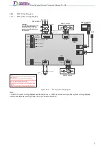
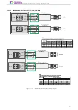
3.4.1.2
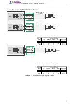
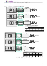
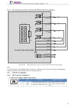
RC2 Encoder Port X4 Wiring Diagram
2EVCC
2DATA+
2DATA-
2GND
B2
A2
A1
B1
VCC[Note2]
GND[Note2]
J2 Encoder
Shielded twisted-pair
wire[Note1]
J2 Encoder
A1
A2
B1
B2
DATA-[Note2]
DATA+[Note2]
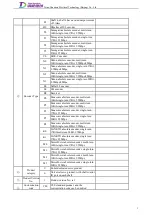
Nikon
Jamagawa
Panasonic
SGNKYO
MotorPower
Vcc
B5V
Vcc
E5V
Vcc
DCB5V
GND
0V
GND
E0V
GND
GND
DGJG-
ES-
/SD
PS
-D
DGJG-
DGJGB
ESB
SD
PS
BD
DGJGB
Drive side
signals
Encoder side signals
Note:
1. The encoder cable shielded wire is connected to the cable bracket.
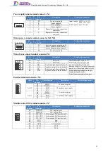
2. See the table below for corresponding encoder side signals
X4-J2
A
B
2
1
1EVCC
1DATA+
1DATA-
1GND
B2
A2
A1
B1
VCC[Note2]
GND[Note2]
J1 Encoder
Shielded twisted-pair
wire[Note1]
J1 Encoder
A1
A2
B1
B2
DATA-[Note2]
DATA+[Note2]
X4-J1
A
B
2
1
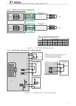
Figure 3.4-2.
RC2 Encoder Port X4 Wiring Diagram
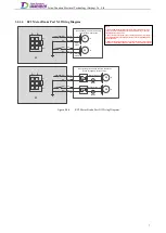
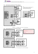
3.4.1.3
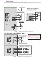
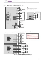
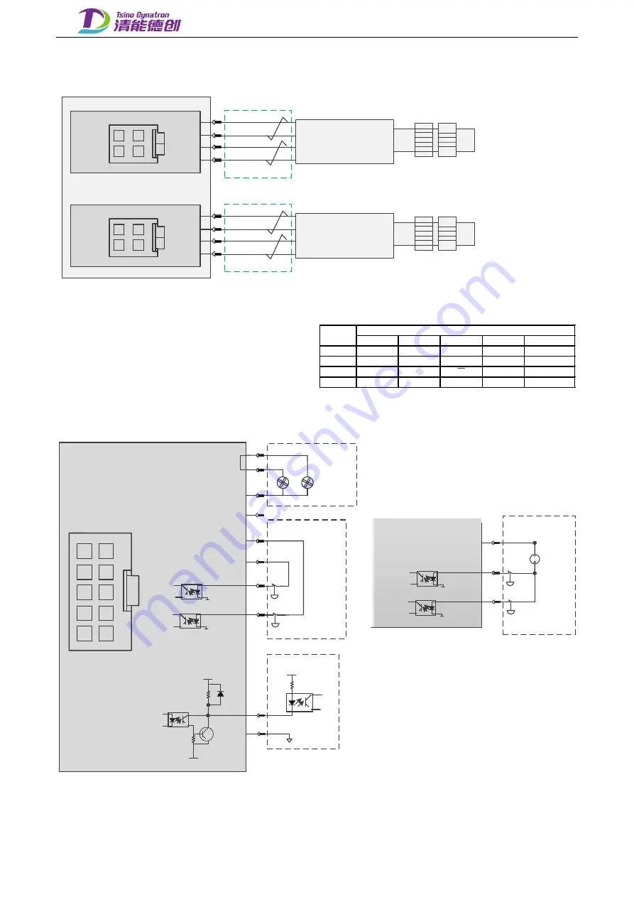
RC2 Module Control I/O Port X7 Wiring Diagram
STO1 B5
A4
A5
24VGND
B4
STO2
24VGND A1
24VGND
+24V_OUT
+24V_OUT
STO internal 24V
power supply
X7
B3
24VGND
/ALM
A1
A2
A3
A4
A5
B1
B2
B3
B4
B5
A3
+24V_OUT
B2
A2
FAN
Fan (optional)
24VGND
B1
FAN
N24V
External power supply
Controller
External power
supply 24VGND
X7
STO1 B5
A1
24VGND
B4
STO2
24VGND
24VGND
STO external 24V
power supply
24VDC
P24V
A
B
1
5
Note:
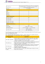
1) The total max. output current of port B1 and B2 is 0.4A
2) The total max. output current of port B3 is 0.1A
3) Port B3 is an output port with active low
4) STO1 and STO2 must be wired as required
Figure 3.4-3.
RC2 Module Control I/O Port X7 Wiring Diagram
6
Summary of Contents for EtherCAT CoolDrive RC Series
Page 1: ...Updated on Update summary Updated version Version number D3 ...
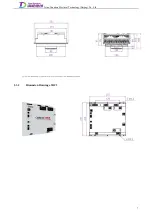
Page 17: ...Tsino Dynatron Electrical Technology Beijing Co Ltd Dimension Drawing of RC3 2 3 2 7 ...
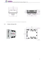
Page 18: ...Tsino Dynatron Electrical Technology Beijing Co Ltd Dimension Drawing of RC4 2 3 3 8 ...
Page 19: ...Tsino Dynatron Electrical Technology Beijing Co Ltd 9 ...
Page 20: ...Tsino Dynatron Electrical Technology Beijing Co Ltd Dimension Drawing of RC6 2 3 4 1 ...


